Ericom Connect URL 自動判別について
URL 自動判別オプションについて
Ericom 製品では、インターネット向けの仮想ブラウザーとイントラネット向けのブラウザーの 2 つの (ダブル) ブラウザーが必要ですが、当該オプションを使うことによって、イントラ・インターネットの自動判別とブラウザーアクセスを実現できます。詳細についてはこちらを参照ください。
URL 自動判別オプション要件
- Microsoft .NET Framework 3.5、または Microsoft .NET 4.* Framework のインストール
- Ericom AccessPad Client のインストール
- Internet Explorer/Chrome/Firefox の最新版のインストール
- クライアント端末が Active Directory に所属
URL 自動判別オプションのユースケース
- ユーザーが Outlook や Adobe Reader といったアプリケーションからリンクをクリックした際、仮想ブラウザーとイントラネット向けブラウザーを識別して起動します。
- ユーザーがイントラネットのブラウザーからインターネットのリンクをクリックした際、URL 自動判別オプションのアドオン・拡張がリンクを AccessPad で開きます。
Ericom Connect 側の設定
対象のアプリケーション(本例では仮想ブラウザの chrome)の「基本」で「パラメータ」に「${param1}」を入力します。*1
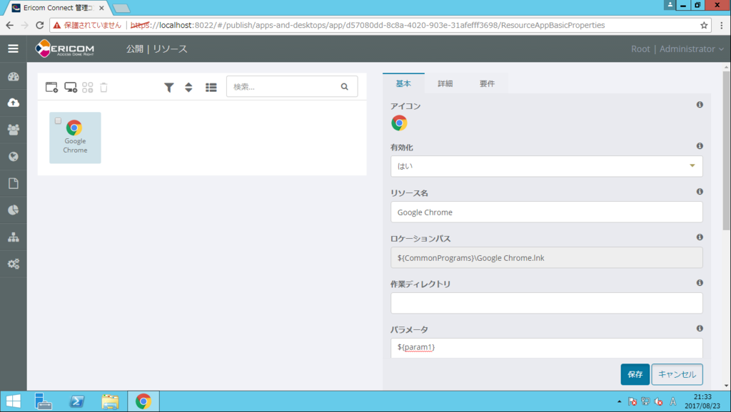
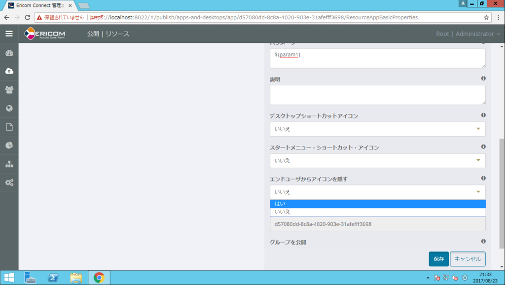
「エンドユーザからアイコンを隠す」を「はい」に変更します。*2
次に「要件」を設定変更します。
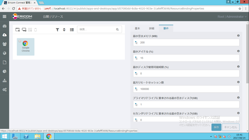
「許可される起動方法」を「標準」から「すべて」に変更します。

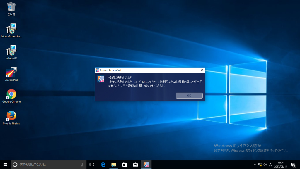
上記設定をしない場合、クライアントで仮想ブラウザの起動に失敗し以下のエラーが出力されます。
接続に失敗しました
操作に失敗しました(コード 6).このリソースは制限のために起動することが出来ません。
システム管理者に問い合わせてください。
URL 自動判別オプションのインストール
インストール方法は以下の2つがあります。
- MSI によるインストール
- 連携キット(ClickOnce 版)による配布
※本例では MSI によるインストールを紹介します。
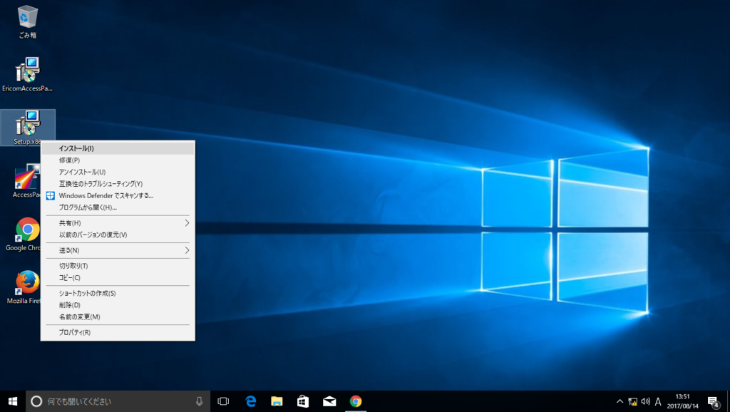
Setup.x86.msi を実行します。
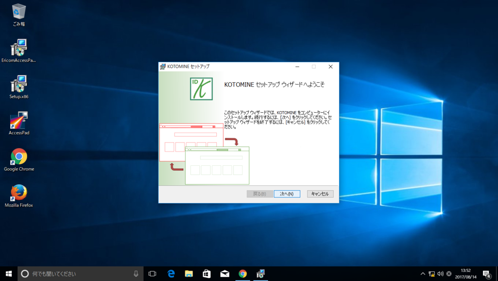
「次へ」をクリックします。
インストールする方法を選択します。
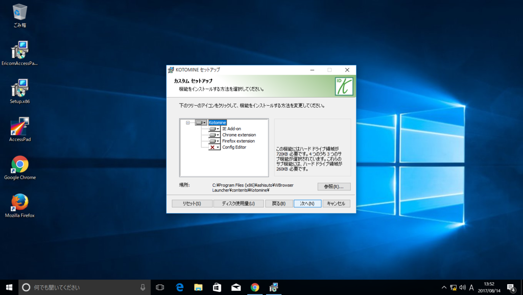
URL を判別して起動方法を変更するための拡張をインストールします。*3
- IE Add-on: Internet Explorer にアドインをインストールします。
- Chrome extensions: Chrome に拡張をインストールします。
- Firefox extension: Firefox に拡張をインストールします。
- Config Editor: KOTOMINE の設定とイントラネット URL の一覧を編集するツールです。*4
設定をカスタマイズします

- イントラネット URL の一覧のファイルパス: URL が記載されたファイルのパスです。
- イントラネットのブラウザー: イントラネットの URL を開くためのブラウザーです。*5
- AccessPad のパラメーター: AccessPad を起動する URI やアプリ名、グループです。
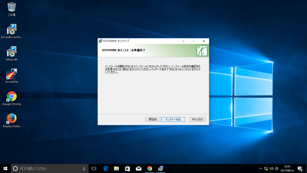
「インストール」ボタンをクリックします。
Windows 8 以上の場合、「プログラムの関連付けを設定する」画面が表示されます。「すべて選択」 のチェックボックスをチェックし、保存ボタンをクリックします。

「完了」をクリックします。

(2017.8.23 追記)上記「プログラムの関連付け」において、既定のブラウザに KOTOMINE の「BrowserLauncher」を指定する必要があります。「BrowserLauncher」が指定されていない場合、PDF 等のリンクをクリックした際に、仮想ブラウザが正常に起動しない場合があります。
Config Editor を起動し「既定のブラウザーとして設定」をクリックします。
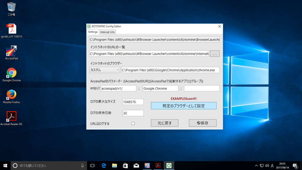
「すべて選択」をチェックし、「保存」をクリックします。

~ここまで~
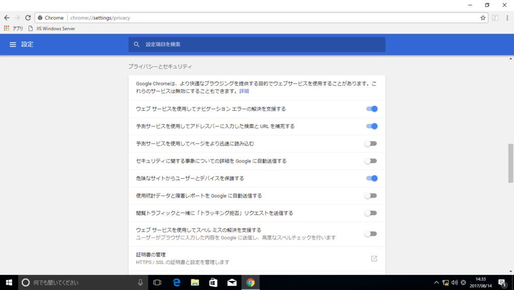
インストール後 (Chrome 拡張がインストールされた場合)
Chrome の予測サービスをオフにします。*6
イントラネット URL リストの編集*7
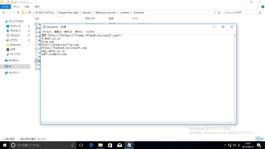
インストール先フォルダーに格納された InternalUrls ファイルをメモ帳などで編集します。
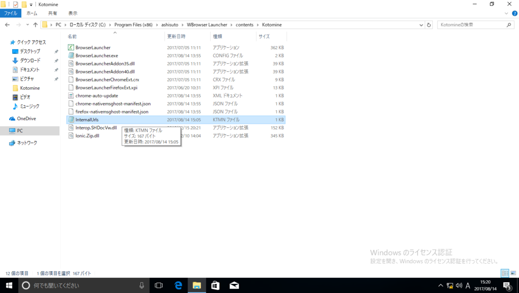
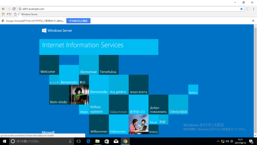
本例では、イントラネット向けサイトとして"ad01.example.com"を設定します。
接続確認
上記 URL へアクセスすると、ローカルブラウザでアクセスします。
URL リストに記載されていない URL(本例では google.com)へアクセスすると、AccessPad を起動し、仮想ブラウザで接続します。

以上
Ericom Connect インストール手順
Ericom Connect とは
Windows Server の Remote Desktop Services(RDS)、VDI などのクライアント仮想化サーバーと、各クライアントを仲介するコネクションブローカーです。詳細についてはこちらを参照ください。
Ericom Connect 要件
各サーバーのシステム要件についてはこちらを参照ください。
Ericom Connect インストールの事前作業
- Ericom Connect サーバーをドメインへ参加させます。
- Ericom Connect サーバーインストール用のアカウントに UPN(User Principal Name)を登録します。

SQL Server 2014 Express をインストールします。*1

「SQL Server Browser」サービスのスタートアップの種類を「自動」に変更します。

認証モードを「混合モード」に変更し、任意の sa アカウント用パスワードを入力します。

他パラメータはデフォルトを使用します。

「SQL Server 2014 構成マネージャー」を起動します。

「プロトコル」の「TCP/IP」を有効にし、SQL Server のサービスを再起動します。

Ericom Connect インストール
EricomConnect.exe を実行します。

「Custom」を選択します。

インストールするコンポーネントを選択します。 本例では RDS を別建てし ESG*2 をインストールしないことを前提としています。

インストール後「Ericom Connect Configuration Tool」が自動で起動するので「Configuration Analyzer」をクリックします。

「Connect Administrator」の項にドメイン管理者パスワードを入力し、「Analyze」をクリックします。

全ての項目が緑色になることを確認し、「Return to Configuration Tool」をクリックします。

「New Grid」をクリックします。

「Grid Name」に任意のグリッド名を入力、Server User のパスワードを任意の値に変更し「Initialize Database..」をクリックします。

「Completed」の表示を確認後、Configuration Tool を終了します。

"https://「Connect サーバーアドレス」:8022/admin" にアクセスし、Connect サーバー管理者でログインします。

管理コンソール画面が表示されます。

RDS サーバーインストールの事前作業
「リモートデスクトップセッションホスト」と「リモートデスクトップライセンス」をインストールします。

「このコンピュータへのリモート接続を許可する」をチェックします。

ユーザの選択で本例では「Domain Users」を選択します。

RDS サーバーへのセッションを、1ユーザで複数セッション接続可能になるように設定します。「ファイル名を指定して実行」にて「gpedit.msc」と入力し、「OK」をクリックします。

ローカルグループポリシーエディターで、「コンピュータの構成」 > 「管理用テンプレート」 > 「Windowsコ ンポーネント」 > 「リモートデスクトップサービス」 > 「リモートデスクトップセッションホスト」 > 「接続」の「リモートデスクトップサービスユーザーに対してリモートデスクトップサービスセッションを1つに制限する」をダブルクリックします。

「無効」にチェックを入れ、「OK」をクリックします。

リモートデスクトップライセンスサーバーを有効化します。「リモートデスクトップライセンスマネージャー」を起動します。

「サーバーのアクティブ化」を選択します。

「ライセンスのインストール ウィザードを開始する」のチェックを外し、「完了」をクリックします。*3

「ファイル名を指定して実行」を起動して「gpedit.msc」と入力し、「OK」をクリックします。

「コンピューターの構成」 > 「管理用テンプレート」 > 「Windows コンポーネント」 > 「リモートデスクトップサービス」 > 「リモートデスクトップセッションホスト」 > 「ライセンス」の「リモートデスクトップライセンスモードの設定」のポリシーをダブルクリックします。

リモートデスクトップライセンスモードを「有効」にし、「接続ユーザ数」を指定し「OK」をクリックします。

次に、リモートデスクトップライセンスサーバーを指定します。

ライセンスサーバーを使用するを有効にし、ライセンスサーバーを指定します。

「gpupdate /force」コマンドを実行し、実行結果にエラーが無いことを確認します。

RemoteAgent のインストール
EricomConnectRemoteHost_x64.exe を実行します。

パラメータはデフォルトを使用します。

インストール後「RemoteAgent Configuration」が自動で起動するので、Connect サーバ導入時に設定したグリッド名を設定します。

Starting service メッセージが表示されることを確認します。

Connect 管理コンソールにログインして、「リソースサーバーのステータス」に RDS が登録されていることを確認します。

「サービス」でグリッドに接続されているサーバの一覧に RDS が登録されていることを確認します。

アプリケーションの公開設定
Connect 管理コンソールにログオンし、「リソース」 > 「アプリケーション追加」をクリックします。

サーバ一覧で、rd01 を選択し、公開するアプリケーション(本例では chrome)を選択し「追加」をクリックします。

公開した「chrome」のアイコンが表示されることを確認します。

「グループ」 > 「グループ追加」をクリックします。

グループ名を設定し、公開するアプリケーションにチェックを入れ「作成」をクリックします。

公開アプリケーションを使用できるユーザを割り当てます。「ユーザ」タブで 「Active Directory オブジェクトを追加」をクリックします。

ドメイン上のグループを指定し「追加」をクリックします。

「Domain Users」に所属しているユーザがアプリケーションを使用可能となります。

「半角/全角」キーの利用を許可する場合、「設定」 > 「デフォルト」 > 「スキャンコードの有効化」を「はい」に変更します。

「Access Portal の言語」と「Access Portal キーボード」に「jajp」と入力し、「保存」をクリックします。

接続確認
AccessPortal を使用したブラウザ接続
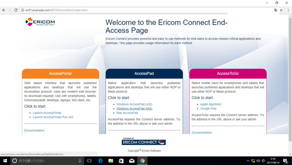
クライアント端末から、"http://「Connect サーバーアドレス」:8033/" にアクセスし、「Launch AcceessPortal」をクリックします。

アカウント情報を入力し、「ログイン」をクリックします。

左ペインの公開アプリケーション(本例では chrome)をクリックします。

ローカルブラウザ内にアプリケーションが起動します。

AccessPad を使用したブラウザ接続
クライアント端末から、"http://「Connect サーバーアドレス」:8033/" にアクセスし、「Windows AccessPad (x64)」をクリックします。
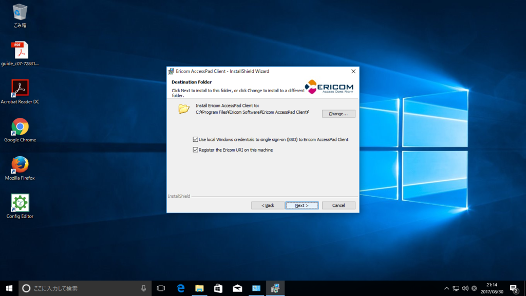
EricomAccessPadClient64.exe をインターネット経由でダウンロードしますのでインストールします。

AccessPad インストール時、「Use Local Windows credentials to SSO..」にチェックを入れてインストールすると、Windows のアカウントで自動ログインができるようになります。*4
インストール直後だけパスワードを入力する必要があります。以後は端末再起動後もログイン作業は省略されます。
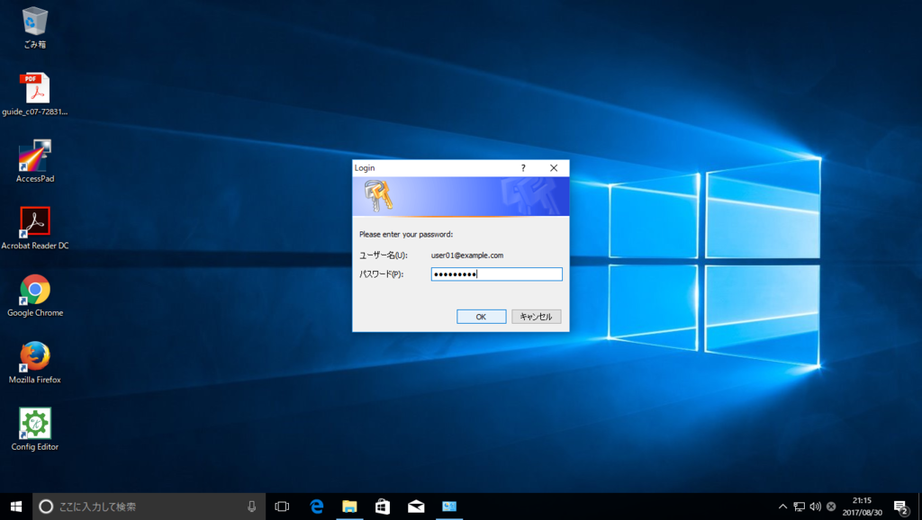
AccessPad を起動し、サーバー、アカウント情報を入力後、「ログイン」をクリックします。サーバー欄は "「Connect サーバアドレス」:8011"と入力します。

公開アプリケーション(本例では chrome)をクリックします。

アプリケーションが起動します。

以上
UCS へ ESXi6.5 をインストールした際に発生した問題について
問題
Cisco の UCS C220 M4S に VMware ESXi6.5(Custom)をインストールしたところ、ネットワークアダプタへ割り当てるデバイス名(vmnicN:N は整数)が予期せぬ形となる問題に遭遇しました。
KB2091560を参考に、デバイス名の割り当てを変更する等色々試しましたが正攻法では回避できず、以下の対策でのみ解決することができました。本対策の妥当性については、今後メーカへ確認予定です。
ESXi6.5 新規インストール後の問題
ESXi のバージョン確認
~ # esxcli system version get
   Product: VMware ESXi
   Version: 6.5.0
   Build: Releasebuild-5310538
   Update: 0
   Patch: 19
インターフェース構成の確認
~ # esxcfg-nics -l
Name    PCI          Driver      Link Speed      Duplex MAC Address       MTU    Description
M1-1 -> vmnic0  0000:06:00.0 igbn        Up   1000Mbps   Full   a0:36:9f:8d:05:4c 1500   Intel Corporation I350 Gigabit Network Connection
M1-2 -> vmnic1  0000:06:00.1 igbn        Down 0Mbps      Half   a0:36:9f:8d:05:4d 1500   Intel Corporation I350 Gigabit Network Connection
M2-1 -> vmnic2  0000:81:00.0 igbn        Up   1000Mbps   Full   a0:36:9f:8f:7a:60 1500   Intel Corporation I350 Gigabit Network Connection
M2-2 -> vmnic3  0000:81:00.1 igbn        Down 0Mbps      Half   a0:36:9f:8f:7a:61 1500   Intel Corporation I350 Gigabit Network Connection
M2-3 -> vmnic4  0000:81:00.2 igbn        Down 0Mbps      Half   a0:36:9f:8f:7a:62 1500   Intel Corporation I350 Gigabit Network Connection
M2-4 -> vmnic5  0000:81:00.3 igbn        Up   1000Mbps   Full   a0:36:9f:8f:7a:63 1500   Intel Corporation I350 Gigabit Network Connection
LOM1 -> vmnic6  0000:01:00.0 igbn        Up   1000Mbps   Full   00:35:1a:10:44:0e 1500   Intel Corporation I350 Gigabit Network Connection
LOM2 -> vmnic7  0000:01:00.1 igbn        Up   1000Mbps   Full   00:35:1a:10:44:0f 1500   Intel Corporation I350 Gigabit Network Connection
M1-3 -> vmnic8  0000:06:00.2 igbn        Down 0Mbps      Half   a0:36:9f:8d:05:4e 1500   Intel Corporation I350 Gigabit Network Connection
M1-4 -> vmnic9  0000:06:00.3 igbn        Up   1000Mbps   Full   a0:36:9f:8d:05:4f 1500   Intel Corporation I350 Gigabit Network Connection
通常では以下のとおり割り当てられますが、上記のとおり想定外の割り当てとなります。
- LOM1 -> vmnic0(LOM1 はオンボード NIC1 の略称)
- LOM2 -> vmnic1(LOM2 はオンボード NIC2 の略称)
- M1-1~4 -> vmnic2~5(M1 はスロット1に挿入されたメザニンカードの略称)
- M1-2~4 -> vmnic6~9(M2 はスロット2に挿入されたメザニンカードの略称)
ネットワークアダプタとエイリアス名の割り当てを表示(上記同様にバラバラです。)
~ # localcli --plugin-dir /usr/lib/vmware/esxcli/int/ deviceInternal alias list | grep vmnic | grep -v logical
M1-1 -> pci       p0000:06:00.0        vmnic0
M1-2 -> pci       p0000:06:00.1        vmnic1
M2-1 -> pci       p0000:81:00.0        vmnic2
M2-2 -> pci       p0000:81:00.1        vmnic3
M2-3 -> pci       p0000:81:00.2        vmnic4
M2-4 -> pci       p0000:81:00.3        vmnic5
LOM1 -> pci       s00000000.00         vmnic6
LOM2 -> pci       s00000000.01         vmnic7
M1-3 -> pci       s00000000.02         vmnic8
M1-3 -> pci       s00000000.03         vmnic9
回避策
本事象は、ESXi5.1では発生せず、またKB2091560にも記載があるとおり、ESXi のアップデートをしてもアップデート前に割り当てたデバイス名は維持されるため、ESXi6.5 を新規インストールせず、5.1からアップデートします。(以下 KB 抜粋)
Upgrades from one release of ESXi to the next, including autodeploy configurations, do not change the aliases previously assigned to the system's ports. This includes upgrading from prior releases to ESXi 5.5 and later.
ESXi5.1 新規インストール後の状態
ESXi のバージョン確認
~ # esxcli system version get
   Product: VMware ESXi
   Version: 5.1.0
   Build: Releasebuild-2323236
   Update: 3
インターフェース構成の確認
~ # esxcfg-nics -l
Name    PCI          Driver      Link Speed      Duplex MAC Address       MTU    Description
LOM1 -> vmnic0  0000:01:00.0 igbn        Up   1000Mbps   Full   00:35:1a:10:44:0e 1500   Intel Corporation I350 Gigabit Network Connection
LOM2 -> vmnic1  0000:01:00.1 igbn        Up   1000Mbps   Full   00:35:1a:10:44:0f 1500   Intel Corporation I350 Gigabit Network Connection
M1-1 -> vmnic2  0000:06:00.0 igbn        Up   1000Mbps   Full   a0:36:9f:8d:05:4c 1500   Intel Corporation I350 Gigabit Network Connection
M1-2 -> vmnic3  0000:06:00.1 igbn        Down 0Mbps      Half   a0:36:9f:8d:05:4d 1500   Intel Corporation I350 Gigabit Network Connection
M1-3 -> vmnic4  0000:06:00.2 igbn        Down 0Mbps      Half   a0:36:9f:8d:05:4e 1500   Intel Corporation I350 Gigabit Network Connection
M1-4 -> vmnic5  0000:06:00.3 igbn        Up   1000Mbps   Full   a0:36:9f:8d:05:4f 1500   Intel Corporation I350 Gigabit Network Connection
M2-1 -> vmnic6  0000:81:00.0 igbn        Up   1000Mbps   Full   a0:36:9f:8f:7a:60 1500   Intel Corporation I350 Gigabit Network Connection
M2-2 -> vmnic7  0000:81:00.1 igbn        Down 0Mbps      Half   a0:36:9f:8f:7a:61 1500   Intel Corporation I350 Gigabit Network Connection
M2-3 -> vmnic8  0000:81:00.2 igbn        Down 0Mbps      Half   a0:36:9f:8f:7a:62 1500   Intel Corporation I350 Gigabit Network Connection
M2-4 -> vmnic9  0000:81:00.3 igbn        Up   1000Mbps   Full   a0:36:9f:8f:7a:63 1500   Intel Corporation I350 Gigabit Network Connection
上記のとおり想定どおりの割り当てとなります。
ESXi5.1 から 6.0U2 へアップデート
ESXi5.1 から 6.5 のアップデートパスはないため、まずは 6.0U2 へアップデートします。
VMware のサイトからアップデートファイルをダウンロードし、SCP 等を利用して対象のホストへ転送します。
本例では、以下のパスへ配置します。
vmfs/volumes/datastore1/update/Vmware-ESXi-6.0.0-3620759-Custom-Cisco-6.0.2.2-Bundle.zip
アップデートファイルを確認
~ # esxcli software sources profile list -d /vmfs/volumes/datastore1/update/Vmware-ESXi-6.0.0-3620759-Custom-Cisco-6.0.2.2-Bundle.zip
Name                                            Vendor  Acceptance Level
----------------------------------------------  ------  ----------------
Vmware-ESXi-6.0.0-3620759-Custom-Cisco-6.0.2.2  Cisco   PartnerSupported
ESXi5.1 から 6.0U2 へアップデート実行
~ # esxcli software profile update -p Vmware-ESXi-6.0.0-3620759-Custom-Cisco-6.0.2.2 -d /vmfs/volumes/datastore1/update/Vmware-ESXi-6.0.0-3620759-Custom-Cisco-6.0.2.2-Bundle.zip
Update Result
   Message: The update completed successfully, but the system needs to be rebooted for the changes to be effective.
   Reboot Required: true
   VIBs Installed:
<...snip...>
再起動
~ # reboot
ESXi5.1 から 6.0U2 アップデート後の状態
ESXi のバージョン確認
~ # esxcli system version get
   Product: VMware ESXi
   Version: 6.0.0
   Build: Releasebuild-3620759
   Update: 2
   Patch: 34
ESXi6.0U2 から 6.5 へアップデート
アップデートファイルを確認
~ #  esxcli software sources profile list -d /vmfs/volumes/datastore1/update/Vmware-ESXi-6.5.0-4564106-Custom-Cisco-6.5.0.2.zip
Name                                            Vendor  Acceptance Level
----------------------------------------------  ------  ----------------
Vmware-ESXi-6.5.0-4564106-Custom-Cisco-6.5.0.2  Cisco   PartnerSupported
ESXi6.0U2 から 6.5 へアップデート実行
~ # esxcli software profile update -p Vmware-ESXi-6.5.0-4564106-Custom-Cisco-6.5.0.2 -d /vmfs/volumes/datastore1/update/Vmware-ESXi-6.5.0-4564106-Custom-Cisco-6.5.0.2.zip
 [DependencyError]
 VIB Emulex_bootbank_scsi-be2iscsi_10.2.250.0-1OEM.500.0.0.472629 requires com.vmware.iscsi_linux-9.2.0.0, but the requirement cannot be satisfied within the ImageProfile.
 VIB QLogic_bootbank_scsi-qla4xxx_634.5.26.0-1OEM.500.0.0.472560 requires com.vmware.driverAPI-9.2.0.0, but the requirement cannot be satisfied within the ImageProfile.
 VIB Emulex_bootbank_scsi-be2iscsi_10.2.250.0-1OEM.500.0.0.472629 requires com.vmware.driverAPI-9.2.0.0, but the requirement cannot be satisfied within the ImageProfile.
 VIB QLogic_bootbank_scsi-qla4xxx_634.5.26.0-1OEM.500.0.0.472560 requires com.vmware.iscsi_linux-9.2.0.0, but the requirement cannot be satisfied within the ImageProfile.
 VIB Emulex_bootbank_scsi-be2iscsi_10.2.250.0-1OEM.500.0.0.472629 requires vmkapi_2_0_0_0, but the requirement cannot be satisfied within the ImageProfile.
 VIB QLogic_bootbank_scsi-qla4xxx_634.5.26.0-1OEM.500.0.0.472560 requires vmkapi_2_0_0_0, but the requirement cannot be satisfied within the ImageProfile.
 Please refer to the log file for more details.
 <...snip...>
依存関係のエラーがでましたが、本例では Emulex や Qlogic 社製のアダプタは使用していないので、以下のコマンドで強制的にアップデートを実行しました。
~ # esxcli software profile update -d /vmfs/volumes/datastore1/update/Vmware-ESXi-6.5.0-4564106-Custom-Cisco-6.5.0.2.zip -p Vmware-ESXi-6.5.0-4564106-Custom-Cisco-6.5.0.2 -f
Update Result
   Message: The update completed successfully, but the system needs to be rebooted for the changes to be effective.
   Reboot Required: true
   VIBs Installed:
 <...snip...>
再起動
~ # reboot
ESXi6.0U2 から 6.5 アップデート後の状態
ESXi のバージョン確認
~ # esxcli system version get
   Product: VMware ESXi
   Version: 6.5.0
   Build: Releasebuild-4564106
   Update: 0
   Patch: 0
インターフェース構成の確認
~ # esxcfg-nics -l
Name    PCI          Driver      Link Speed      Duplex MAC Address       MTU    Description
LOM1 -> vmnic0  0000:01:00.0 igbn        Up   1000Mbps   Full   00:35:1a:10:44:0e 1500   Intel Corporation I350 Gigabit Network Connection
LOM2 -> vmnic1  0000:01:00.1 igbn        Up   1000Mbps   Full   00:35:1a:10:44:0f 1500   Intel Corporation I350 Gigabit Network Connection
M1-1 -> vmnic2  0000:06:00.0 igbn        Up   1000Mbps   Full   a0:36:9f:8d:05:4c 1500   Intel Corporation I350 Gigabit Network Connection
M1-2 -> vmnic3  0000:06:00.1 igbn        Down 0Mbps      Half   a0:36:9f:8d:05:4d 1500   Intel Corporation I350 Gigabit Network Connection
M1-3 -> vmnic4  0000:06:00.2 igbn        Down 0Mbps      Half   a0:36:9f:8d:05:4e 1500   Intel Corporation I350 Gigabit Network Connection
M1-4 -> vmnic5  0000:06:00.3 igbn        Up   1000Mbps   Full   a0:36:9f:8d:05:4f 1500   Intel Corporation I350 Gigabit Network Connection
M2-1 -> vmnic6  0000:81:00.0 igbn        Up   1000Mbps   Full   a0:36:9f:8f:7a:60 1500   Intel Corporation I350 Gigabit Network Connection
M2-2 -> vmnic7  0000:81:00.1 igbn        Down 0Mbps      Half   a0:36:9f:8f:7a:61 1500   Intel Corporation I350 Gigabit Network Connection
M2-3 -> vmnic8  0000:81:00.2 igbn        Down 0Mbps      Half   a0:36:9f:8f:7a:62 1500   Intel Corporation I350 Gigabit Network Connection
M2-4 -> vmnic9  0000:81:00.3 igbn        Up   1000Mbps   Full   a0:36:9f:8f:7a:63 1500   Intel Corporation I350 Gigabit Network Connection
上記のとおり想定どおりの割り当てが維持されます。
ネットワークアダプタとエイリアス名の割り当てを表示(上記同様に維持されます。)
~ # localcli --plugin-dir /usr/lib/vmware/esxcli/int/ deviceInternal alias list | grep vmnic | grep -v logical
LOM1 -> pci       s00000000.00         vmnic0
LOM2 -> pci       s00000000.01         vmnic1
M1-1 -> pci       p0000:06:00.0        vmnic2
M1-2 -> pci       p0000:06:00.1        vmnic3
M1-3 -> pci       s00000000.02         vmnic4
M1-4 -> pci       s00000000.03         vmnic5
M2-1 -> pci       p0000:81:00.0        vmnic6
M2-2 -> pci       p0000:81:00.1        vmnic7
M2-3 -> pci       p0000:81:00.2        vmnic8
M2-4 -> pci       p0000:81:00.3        vmnic9
ランサムウェアについて
ランサムウェアとは
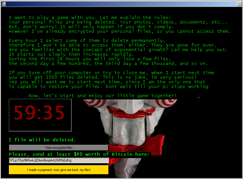
ランサムウェアは機器、ネットワーク、データセンターに感染し、ユーザーや組織が身代金を支払うまで、システムをロックさせ使用できない状態にするタイプのマルウェアです。
ランサムウェアは通常、いくつかあるパターンのうち1つを使って実行されます。
Crypto ランサムウェアは、オペレーティングシステムに感染し、機器が起動できなくなるようにします。
他にも、ドライブやファイル、ファイル名を暗号化するランサムウェアもあります。悪意のあるものにはタイマーが付いたバージョンもあり、身代金が支払われるまでファイルを削除していきます。
すべてにおいて言えるのは、ブロックした、あるいは暗号化したシステム、ファイル、データのロック解除や解放と引き換えに、身代金を支払うよう要求してくる、ということです。
出典:ランサムウェアから身を守るための10の措置
感染後、ユーザーの機器のスクリーン上に以下のようなメッセージが表示されるケースが多いということです。
WannaCry について
概要
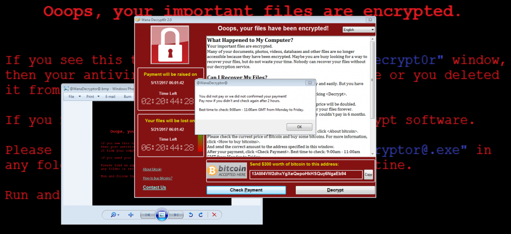
2017年5月に世界各地で爆発的な被害を与えたワーム活動を行うランサムウェアです。*1
感染すると主要なデータファイルを暗号化し、解除するためにビットコインを支払うよう指示されます。
WannaCry 感染によるユーザ表示画面
感染経路
ランサムウェアのファイル自身は Windows 実行形式ファイルになります。メールや不正なウェブサイト経由で拡散しています。CVE-2017-0145(SMBv1の脆弱性)を利用して LAN 内、そしてインターネット上のランダムな宛先に対して広範囲に感染活動を広げます。
感染後の更なる感染活動が、大きな被害を生み出したポイントになっています。
WannaCry の被害状況(2017.6.28時点)

特徴
- ファイル共有機能の脆弱性が修正されていない Windows が対象
- ネットワークベースの攻撃、バックドア等を利用して、社内 LAN、インターネットを通じて拡散
- Tor*2を利用し、C2サーバへ接続
- 日本語を含む27の言語に対応した脅迫文
- Bitcoin で300~600米ドルを要求
- イギリスの医療機関やロシアを始め、世界中で感染被害が報告
- キルスイッチを搭載(詳細は以下のとおり)
対策
- Windows Update で MS17-010 (2017年3月公開) を適用する。
- SMBv1を無効化する。
- UTM をインターネットの出口に設置し、IPS、AntiVirus を有効にする。(インターネット側からの感染活動については、 ルータやファイアウォールで445ポートをブロックするだけで防げますが、ローカルからインターネットアクセスした際の戻りで発生する感染活動には対応できないため、推奨)
キルスイッチについて
WannaCry の活動を停止するトリガーをさします。トリガーは以下のドメインにアクセスできるかどうかです。
www[.]iuqerfsodp9ifjaposdfjhgosurijfaewrwergwea[.]com
WannaCry は、Windows 端末に感染後、上述のドメインにアクセスし、アクセスできなければ活動を開始。アクセスできる場合には活動を停止します。WannaCry が出回った当初は未登録のドメインだったので、IPアドレスが存在せず、感染が拡大しましたが、ある研究者が上記ドメインを取得したため、一部の環境を除いて無効化されたようです。
なぜ、ウィルス製作者がこのような機能を実装したか原因は不明ですが、サンドボックス回避のためと考えられています。(サンドボックスはウイルスが要求したアドレス解決に対して(未登録のドメインであっても)必ずダミー用サーバーのIPアドレスを返すため。)
参考:ITPro
以上
プロキシ ARP について
プロキシ ARP とは
プロキシ ARP とは、ホスト(通常はルータ)が、別のマシンに宛てられた ARP 要求に応答する技法です。 ルータは自分の ID を「偽装する」ことによって、「実際の」送信先にパケットをルーティングする責任を引き受けます。 プロキシ ARP を使用することで、ルーティングやデフォルトゲートウェイの設定を必要とせずに、サブネット上のマシンがリモートサブネットに到達できるようになります。
参考:Cisco トラブルシューティングテクニカルノーツ
元々、サブネットマスクを認識しない旧式のホストのために使用されていた機能です。

プロキシ ARP の実装例
インターフェースに以下の設定を行うことで、有効化します。Cisco ではデフォルトで有効となっています。
Router(config)# interface gigabitEthernet 0/1
Router(config-if)# ip proxy-arp
プロキシ ARP の注意点
サブネットを誤っていたり、Default Gateway なしでも通信が可能となることから、「予期せぬ通信」が発生する可能性があり、(あくまで個人的な意見ですが)特に理由がない場合は無効化を推奨します。
以上
Cross-Stack Etherchannel について
StackWise 機能とは
StackWise 機能は、2台以上の Catalyst を1台の論理スイッチとして運用するクラスタ技術です。最大で9台のスイッチから構成され、そのうち1台がマスターとなり全体の管理を行います。マスター以外のスイッチはメンバーと呼ばれます。詳細については、以下を参照ください。
Cisco StackWise および StackWise Plus テクノロジー
Cross-Stack EtherChannelについて
Stack 構成のスイッチ群において、筐体跨ぎで Link Aggregation を構成する事が可能です。Cisco はこれを Cross-Stack EtherChannel と呼んでいます。注意点として、Cross-Stack EtherChannel では、PAgP をサポートしません。LACP は、IOS 12.2(25)SEC 以降ではサポートします。
IOS バージョンが不明な際等は、on 設定が無難です。
なお、Cross-Stack EtherChannel で PAgP を設定すると、以下のエラーが出力されます。
%With PAgP enabled, all ports in the Channel should belong to the same switch
Command rejected (Port-channel"Number", "Interface Port"): Invalid etherchnl mode
以上
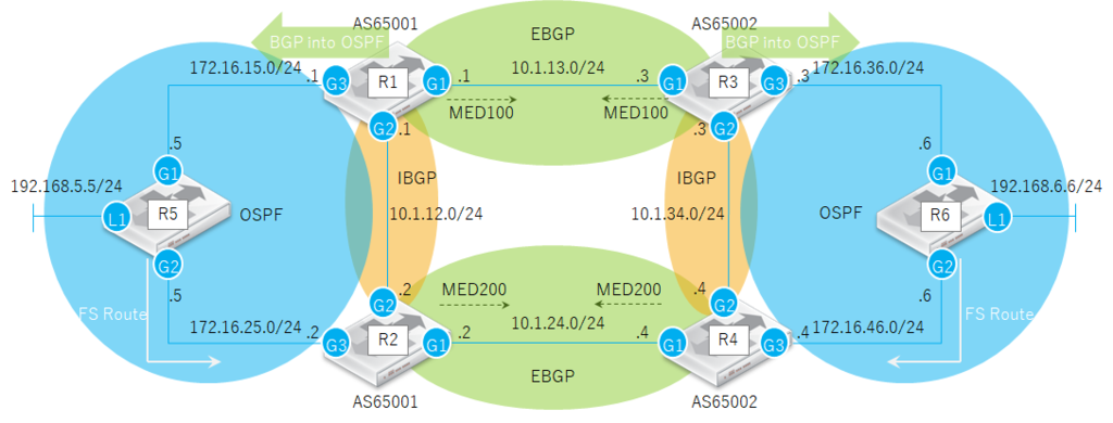
BGP 設定例
概要
BGP を使った冗長化設定例になります。
動作確認は R5 と R6 の Loopback インターフェース間の Ping 疎通により行っています。
検証環境
- CSR1000V を VMware Workstation 上に構築
- IOS は 15.4(1)S2を使用
通信フロー
正常系

故障系-1

故障系-2

故障系-3

設定例
R1
hostname R1
!
interface GigabitEthernet1
 ip address 10.1.13.1 255.255.255.0
 negotiation auto
!
interface GigabitEthernet2
 ip address 10.1.12.1 255.255.255.0
 negotiation auto
!
interface GigabitEthernet3
 ip address 172.16.15.1 255.255.255.0
 negotiation auto
!
router ospf 1
 redistribute bgp 65001 metric 100 metric-type 1 subnets
 network 172.16.15.0 0.0.0.255 area 0
!
router bgp 65001
 bgp log-neighbor-changes
 timers bgp 10 30
 neighbor 10.1.12.2 remote-as 65001
 neighbor 10.1.13.3 remote-as 65002
 !
 address-family ipv4
  bgp redistribute-internal
  network 192.168.5.0
  neighbor 10.1.12.2 activate
  neighbor 10.1.12.2 next-hop-self
  neighbor 10.1.13.3 activate
  neighbor 10.1.13.3 route-map LP in
  neighbor 10.1.13.3 route-map MED out
  neighbor 10.1.13.3 filter-list 1 out
 exit-address-family
!
ip as-path access-list 1 permit ^$
ip as-path access-list 2 permit ^65002_
!
access-list 1 permit 192.168.5.0 0.0.0.255
!
route-map LP permit 10
 match as-path 2
 set local-preference 200
!
route-map MED permit 10
 match ip address 1
 set metric 110
!
R2
hostname R2
!
interface GigabitEthernet1
 ip address 10.1.24.2 255.255.255.0
 negotiation auto
!
interface GigabitEthernet2
 ip address 10.1.12.2 255.255.255.0
 negotiation auto
!
interface GigabitEthernet3
 ip address 172.16.25.2 255.255.255.0
 negotiation auto
!
router ospf 1
 network 172.16.25.0 0.0.0.255 area 0
!
router bgp 65001
 bgp log-neighbor-changes
 timers bgp 10 30
 neighbor 10.1.12.1 remote-as 65001
 neighbor 10.1.24.4 remote-as 65002
 !
 address-family ipv4
  network 192.168.5.0
  neighbor 10.1.12.1 activate
  neighbor 10.1.12.1 next-hop-self
  neighbor 10.1.24.4 activate
  neighbor 10.1.24.4 route-map LP in
  neighbor 10.1.24.4 route-map MED out
  neighbor 10.1.24.4 filter-list 1 out
  distance bgp 20 100 200
 exit-address-family
!
ip as-path access-list 1 permit ^$
ip as-path access-list 2 permit ^65002_
!
access-list 1 permit 192.168.5.0 0.0.0.255
!
route-map LP permit 10
 match as-path 2
 set local-preference 150
!
route-map MED permit 10
 match ip address 1
 set metric 120
!
R3
hostname R3
!
interface GigabitEthernet1
 ip address 10.1.13.3 255.255.255.0
 negotiation auto
!
interface GigabitEthernet2
 ip address 10.1.34.3 255.255.255.0
 negotiation auto
!
interface GigabitEthernet3
 ip address 172.16.36.3 255.255.255.0
 negotiation auto
!
router ospf 1
 redistribute bgp 65002 metric 100 metric-type 1 subnets
 network 172.16.36.0 0.0.0.255 area 0
!
router bgp 65002
 bgp log-neighbor-changes
 timers bgp 10 30
 neighbor 10.1.13.1 remote-as 65001
 neighbor 10.1.34.4 remote-as 65002
 !
 address-family ipv4
  bgp redistribute-internal
  network 192.168.6.0
  neighbor 10.1.13.1 activate
  neighbor 10.1.13.1 route-map LP in
  neighbor 10.1.13.1 route-map MED out
  neighbor 10.1.13.1 filter-list 1 out
  neighbor 10.1.34.4 activate
  neighbor 10.1.34.4 next-hop-self
 exit-address-family
!
ip as-path access-list 1 permit ^$
ip as-path access-list 2 permit ^65001_
!
access-list 1 permit 192.168.6.0 0.0.0.255
!
route-map LP permit 10
 match as-path 2
 set local-preference 200
!
route-map MED permit 10
 match ip address 1
 set metric 110
!
R4
hostname R4
!
interface GigabitEthernet1
 ip address 10.1.24.4 255.255.255.0
 negotiation auto
!
interface GigabitEthernet2
 ip address 10.1.34.4 255.255.255.0
 negotiation auto
!
interface GigabitEthernet3
 ip address 172.16.46.4 255.255.255.0
 negotiation auto
!
router ospf 1
 network 172.16.46.0 0.0.0.255 area 0
!
router bgp 65002
 bgp log-neighbor-changes
 timers bgp 10 30
 neighbor 10.1.24.2 remote-as 65001
 neighbor 10.1.34.3 remote-as 65002
 !
 address-family ipv4
  network 192.168.6.0
  neighbor 10.1.24.2 activate
  neighbor 10.1.24.2 route-map LP in
  neighbor 10.1.24.2 route-map MED out
  neighbor 10.1.24.2 filter-list 1 out
  neighbor 10.1.34.3 activate
  neighbor 10.1.34.3 next-hop-self
  distance bgp 20 100 200
 exit-address-family
!
ip as-path access-list 1 permit ^$
ip as-path access-list 2 permit ^65001_
!
access-list 1 permit 192.168.6.0 0.0.0.255
!
route-map LP permit 10
 match as-path 2
 set local-preference 150
!
route-map MED permit 10
 match ip address 1
 set metric 120
!
R5
hostname R5
!
interface Loopback1
 ip address 192.168.5.5 255.255.255.0
 ip ospf network point-to-point
!
interface GigabitEthernet1
 ip address 172.16.15.5 255.255.255.0
 negotiation auto
!
interface GigabitEthernet2
 ip address 172.16.25.5 255.255.255.0
 negotiation auto
!
router ospf 1
 network 172.16.15.0 0.0.0.255 area 0
 network 172.16.25.0 0.0.0.255 area 0
 network 192.168.5.0 0.0.0.255 area 0
!
ip route 192.168.6.0 255.255.255.0 172.16.25.2 200
!
R6
hostname R6
!
interface Loopback1
 ip address 192.168.6.6 255.255.255.0
 ip ospf network point-to-point
!
interface GigabitEthernet1
 ip address 172.16.36.6 255.255.255.0
 negotiation auto
!
interface GigabitEthernet2
 ip address 172.16.46.6 255.255.255.0
 negotiation auto
!
router ospf 1
 network 172.16.36.0 0.0.0.255 area 0
 network 172.16.46.0 0.0.0.255 area 0
 network 192.168.6.0 0.0.0.255 area 0
!
ip route 192.168.5.0 255.255.255.0 172.16.46.4 200168.6.0 255.255.255.0 172.16.25.2 200
!
設定のポイント
R1(R3)
- IBGP の経路情報を OSPF へ再配送
 address-family ipv4
  bgp redistribute-internal
共通
- 他の AS の経路情報を配送しない。
 address-family ipv4
  neighbor 10.1.13.3 filter-list 1 out
!
ip as-path access-list 1 permit ^$
動作確認
正常系
R1(R3)は、対向へ経路情報を配信
R1#show ip bgp neighbors 10.1.13.3 advertised-routes
BGP table version is 4, local router ID is 192.168.1.221
Status codes: s suppressed, d damped, h history, * valid, > best, i - internal,
              r RIB-failure, S Stale, m multipath, b backup-path, f RT-Filter,
              x best-external, a additional-path, c RIB-compressed,
Origin codes: i - IGP, e - EGP, ? - incomplete
RPKI validation codes: V valid, I invalid, N Not found

     Network          Next Hop            Metric LocPrf Weight Path
 *>  192.168.5.0      172.16.15.5              2         32768 i

Total number of prefixes 1
R1(R3)は、対向から経路情報を受信
R1#show ip bgp neighbors 10.1.13.3 routes
BGP table version is 4, local router ID is 192.168.1.221
Status codes: s suppressed, d damped, h history, * valid, > best, i - internal,
              r RIB-failure, S Stale, m multipath, b backup-path, f RT-Filter,
              x best-external, a additional-path, c RIB-compressed,
Origin codes: i - IGP, e - EGP, ? - incomplete
RPKI validation codes: V valid, I invalid, N Not found

     Network          Next Hop            Metric LocPrf Weight Path
 *>  192.168.6.0      10.1.13.3              110    200      0 65002 i

Total number of prefixes 1
R1(R3)は、LAN 内のネットワークについて OSPF 経由の経路を使用
R1#show ip route 192.168.5.0 longer-prefixes
Codes: L - local, C - connected, S - static, R - RIP, M - mobile, B - BGP
       D - EIGRP, EX - EIGRP external, O - OSPF, IA - OSPF inter area
       N1 - OSPF NSSA external type 1, N2 - OSPF NSSA external type 2
       E1 - OSPF external type 1, E2 - OSPF external type 2
       i - IS-IS, su - IS-IS summary, L1 - IS-IS level-1, L2 - IS-IS level-2
       ia - IS-IS inter area, * - candidate default, U - per-user static route
       o - ODR, P - periodic downloaded static route, H - NHRP, l - LISP
       a - application route
       + - replicated route, % - next hop override

Gateway of last resort is not set

O     192.168.5.0/24 [110/2] via 172.16.15.5, 06:44:10, GigabitEthernet3
R1(R3)は、対向のネットワークについて BGP 経由の経路を使用
R1#show ip route 192.168.6.0 longer-prefixes
Codes: L - local, C - connected, S - static, R - RIP, M - mobile, B - BGP
       D - EIGRP, EX - EIGRP external, O - OSPF, IA - OSPF inter area
       N1 - OSPF NSSA external type 1, N2 - OSPF NSSA external type 2
       E1 - OSPF external type 1, E2 - OSPF external type 2
       i - IS-IS, su - IS-IS summary, L1 - IS-IS level-1, L2 - IS-IS level-2
       ia - IS-IS inter area, * - candidate default, U - per-user static route
       o - ODR, P - periodic downloaded static route, H - NHRP, l - LISP
       a - application route
       + - replicated route, % - next hop override

Gateway of last resort is not set

B     192.168.6.0/24 [20/110] via 10.1.13.3, 00:29:35
R2(R4)は、対向のネットワークについて R1(R3)経由の経路を使用(LocPrf により優先)
R2#show ip bgp
BGP table version is 3, local router ID is 192.168.1.222
Status codes: s suppressed, d damped, h history, * valid, > best, i - internal,
              r RIB-failure, S Stale, m multipath, b backup-path, f RT-Filter,
              x best-external, a additional-path, c RIB-compressed,
Origin codes: i - IGP, e - EGP, ? - incomplete
RPKI validation codes: V valid, I invalid, N Not found

     Network          Next Hop            Metric LocPrf Weight Path
 *>i 192.168.5.0      10.1.12.1                2    100      0 i
 *   192.168.6.0      10.1.24.4              120    150      0 65002 i
 *>i                  10.1.12.1              110    200      0 65002 i
故障系-1
R1(R3)は、対向のネットワークについて R2(R4)経由の経路へ変更
R1#show ip bgp
BGP table version is 8, local router ID is 192.168.1.221
Status codes: s suppressed, d damped, h history, * valid, > best, i - internal,
              r RIB-failure, S Stale, m multipath, b backup-path, f RT-Filter,
              x best-external, a additional-path, c RIB-compressed,
Origin codes: i - IGP, e - EGP, ? - incomplete
RPKI validation codes: V valid, I invalid, N Not found

     Network          Next Hop            Metric LocPrf Weight Path
 *>  192.168.5.0      172.16.15.5              2         32768 i
 *>i 192.168.6.0      10.1.12.2              120    150      0 65002 i
R2(R4)は、対向のネットワークについて R4(R2)経由の経路へ変更
R2#show ip bgp
BGP table version is 4, local router ID is 192.168.1.222
Status codes: s suppressed, d damped, h history, * valid, > best, i - internal,
              r RIB-failure, S Stale, m multipath, b backup-path, f RT-Filter,
              x best-external, a additional-path, c RIB-compressed,
Origin codes: i - IGP, e - EGP, ? - incomplete
RPKI validation codes: V valid, I invalid, N Not found

     Network          Next Hop            Metric LocPrf Weight Path
 *>i 192.168.5.0      10.1.12.1                2    100      0 i
 *>  192.168.6.0      10.1.24.4              120    150      0 65002 i
故障系-2
R1(R3)は、LAN 内のネットワークについて BGP 経由の経路へ変更
R1#show ip route 192.168.5.0 longer-prefixes
Codes: L - local, C - connected, S - static, R - RIP, M - mobile, B - BGP
       D - EIGRP, EX - EIGRP external, O - OSPF, IA - OSPF inter area
       N1 - OSPF NSSA external type 1, N2 - OSPF NSSA external type 2
       E1 - OSPF external type 1, E2 - OSPF external type 2
       i - IS-IS, su - IS-IS summary, L1 - IS-IS level-1, L2 - IS-IS level-2
       ia - IS-IS inter area, * - candidate default, U - per-user static route
       o - ODR, P - periodic downloaded static route, H - NHRP, l - LISP
       a - application route
       + - replicated route, % - next hop override

Gateway of last resort is not set

B     192.168.5.0/24 [200/2] via 10.1.12.2, 00:13:30
R2(R4)は、LAN 内のネットワークについて OSPF 経由の経路へ変更
R2#show ip route 192.168.5.0 longer-prefixes
Codes: L - local, C - connected, S - static, R - RIP, M - mobile, B - BGP
       D - EIGRP, EX - EIGRP external, O - OSPF, IA - OSPF inter area
       N1 - OSPF NSSA external type 1, N2 - OSPF NSSA external type 2
       E1 - OSPF external type 1, E2 - OSPF external type 2
       i - IS-IS, su - IS-IS summary, L1 - IS-IS level-1, L2 - IS-IS level-2
       ia - IS-IS inter area, * - candidate default, U - per-user static route
       o - ODR, P - periodic downloaded static route, H - NHRP, l - LISP
       a - application route
       + - replicated route, % - next hop override

Gateway of last resort is not set

O     192.168.5.0/24 [110/2] via 172.16.25.5, 00:24:05, GigabitEthernet3
故障系-3
R2(R4)は、LAN 内のネットワークについて OSPF 経由の経路へ変更
R2#show ip route 192.168.5.0 longer-prefixes
Codes: L - local, C - connected, S - static, R - RIP, M - mobile, B - BGP
       D - EIGRP, EX - EIGRP external, O - OSPF, IA - OSPF inter area
       N1 - OSPF NSSA external type 1, N2 - OSPF NSSA external type 2
       E1 - OSPF external type 1, E2 - OSPF external type 2
       i - IS-IS, su - IS-IS summary, L1 - IS-IS level-1, L2 - IS-IS level-2
       ia - IS-IS inter area, * - candidate default, U - per-user static route
       o - ODR, P - periodic downloaded static route, H - NHRP, l - LISP
       a - application route
       + - replicated route, % - next hop override

Gateway of last resort is not set

O     192.168.5.0/24 [110/2] via 172.16.25.5, 00:24:05, GigabitEthernet3
R2(R4)は、対向のネットワークについて R4(R2)経由の経路へ変更
R2#show ip route 192.168.6.0 longer-prefixes
Codes: L - local, C - connected, S - static, R - RIP, M - mobile, B - BGP
       D - EIGRP, EX - EIGRP external, O - OSPF, IA - OSPF inter area
       N1 - OSPF NSSA external type 1, N2 - OSPF NSSA external type 2
       E1 - OSPF external type 1, E2 - OSPF external type 2
       i - IS-IS, su - IS-IS summary, L1 - IS-IS level-1, L2 - IS-IS level-2
       ia - IS-IS inter area, * - candidate default, U - per-user static route
       o - ODR, P - periodic downloaded static route, H - NHRP, l - LISP
       a - application route
       + - replicated route, % - next hop override

Gateway of last resort is not set

B     192.168.6.0/24 [20/120] via 10.1.24.4, 00:06:25
R3は、対向のネットワークについて R4 経由の経路へ変更
R3#show ip bgp
BGP table version is 8, local router ID is 192.168.1.223
Status codes: s suppressed, d damped, h history, * valid, > best, i - internal,
              r RIB-failure, S Stale, m multipath, b backup-path, f RT-Filter,
              x best-external, a additional-path, c RIB-compressed,
Origin codes: i - IGP, e - EGP, ? - incomplete
RPKI validation codes: V valid, I invalid, N Not found

     Network          Next Hop            Metric LocPrf Weight Path
 *>i 192.168.5.0      10.1.34.4              120    150      0 65001 i
 *>  192.168.6.0      172.16.36.6              2         32768 i
R5(R6)は、対向のネットワークについて R2(R4)経由の経路へ変更
R5#show ip static route
Codes: M - Manual static, A - AAA download, N - IP NAT, D - DHCP,
       G - GPRS, V - Crypto VPN, C - CASA, P - Channel interface processor,
       B - BootP, S - Service selection gateway
       DN - Default Network, T - Tracking object
       L - TL1, E - OER, I - iEdge
       D1 - Dot1x Vlan Network, K - MWAM Route
       PP - PPP default route, MR - MRIPv6, SS - SSLVPN
       H - IPe Host, ID - IPe Domain Broadcast
       U - User GPRS, TE - MPLS Traffic-eng, LI - LIIN
       IR - ICMP Redirect
Codes in []: A - active, N - non-active, B - BFD-tracked, D - Not Tracked, P - permanent

Static local RIB for default

M  192.168.6.0/24 [200/0] via 172.16.25.2 [A]
以上
*1:OSPF(AD110)経由で学習した経路より IBGP 経由で学習した経路を優先するため。
ASA と VyOS で IPsec
VyOS とは
VyOS は Vyattaの無償版である Vyatta Core よりフォークされたオープンソースのネットワーク OS です。
Cisco の ASA(HA 構成)と VyOS 間で IPsec を確立する際の設定例になります。
検証環境
- VyOS1.1.7 及び、CentOS6.8 を VMware Workstation 上に構築
- VMware ESXi5.5 を VMweare Workstation 上に構築し、ESXi5.5 上に ASAv を構築*1

ASA 設定例
HA 関連の最終設定
※HA の具体的な設定方法は、こちらをご参照ください。
<...snip...>
interface GigabitEthernet0/0
 nameif inside
 security-level 100
 ip address 192.168.10.1 255.255.255.0 standby 192.168.10.2
!
interface GigabitEthernet0/1
 nameif outside
 security-level 0
 ip address 10.1.2.1 255.255.255.0 standby 10.1.2.2
!
interface GigabitEthernet0/2
 description LAN Failover Interface
!
interface GigabitEthernet0/3
 description STATE Failover Interface
<...snip...>
failover
failover lan interface failover GigabitEthernet0/2
failover link state GigabitEthernet0/3
failover interface ip failover 172.16.1.1 255.255.255.0 standby 172.16.1.2
failover interface ip state 172.16.2.1 255.255.255.0 standby 172.16.2.2
<...snip...>
HA の確認
ciscoasa# show failover
Failover On
Failover unit Primary
Failover LAN Interface: failover GigabitEthernet0/2 (up)
Unit Poll frequency 1 seconds, holdtime 15 seconds
Interface Poll frequency 5 seconds, holdtime 25 seconds
Interface Policy 1
Monitored Interfaces 3 of 61 maximum
Version: Ours 9.2(0)2, Mate 9.2(0)2
Last Failover at: 02:57:55 UTC Sep 19 2016
        This host: Primary - Active
                Active time: 27 (sec)
                slot 0: empty
                  Interface inside (192.168.10.1): Normal (Monitored)
                  Interface outside (10.1.2.1): Normal (Monitored)
                  Interface management (192.168.1.101): Normal (Monitored)
        Other host: Secondary - Standby Ready
                Active time: 12455 (sec)
                  Interface inside (192.168.10.2): Normal (Monitored)
                  Interface outside (10.1.2.2): Normal (Monitored)
                  Interface management (192.168.1.102): Normal (Monitored)
<...snip...>
ルートの設定
route outside 10.1.1.0 255.255.255.0 10.1.2.254 1
route outside 192.168.20.0 255.255.255.0 10.1.2.254 1
IPsec の設定
IKE ポリシーの定義及び有効化
crypto ikev1 policy 10
 authentication pre-share
 encryption aes
 hash sha
 group 2
 lifetime 86400
crypto ikev1 enable outside
Tunnel Group (LAN-to-LAN プロファイル)の作成
tunnel-group 10.1.1.2 type ipsec-l2l
tunnel-group 10.1.1.2 ipsec-attributes
 ikev1 pre-shared-key cisco
セレクタ ACL の設定
object-group network local-network
 network-object 192.168.10.0 255.255.255.0
object-group network remote-network
 network-object 192.168.20.0 255.255.255.0
access-list asa-router-vpn extended permit ip object-group local-network object-group remote-network
NAT 除外設定
nat (inside,outside) source static local-network local-network destination static remote-network remote-network no-proxy-arp route-lookup
IKE トランスフォーム設定
crypto ipsec ikev1 transform-set ESP-AES-SHA esp-aes esp-sha-hmac
Crypto MAP の設定とインターフェースへの適用
crypto map outside_map 10 match address asa-router-vpn
crypto map outside_map 10 set peer 10.1.1.2
crypto map outside_map 10 set ikev1 transform-set ESP-AES-SHA
crypto map outside_map interface outside
IPsec 関連の最終設定
<...snip...>
object-group network local-network
 network-object 192.168.10.0 255.255.255.0
object-group network remote-network
 network-object 192.168.20.0 255.255.255.0
access-list asa-router-vpn extended permit ip object-group local-network object-group remote-network
<...snip...>
nat (inside,outside) source static local-network local-network destination static remote-network remote-network no-proxy-arp route-lookup
<...snip...>
crypto ipsec ikev1 transform-set ESP-AES-SHA esp-aes esp-sha-hmac
crypto map outside_map 10 match address asa-router-vpn
crypto map outside_map 10 set pfs
crypto map outside_map 10 set peer 10.1.1.2
crypto map outside_map 10 set ikev1 transform-set ESP-AES-SHA
crypto map outside_map 10 set security-association lifetime seconds 28800
crypto map outside_map interface outside
crypto ikev1 enable outside
crypto ikev1 policy 10
 authentication pre-share
 encryption aes
 hash sha
 group 2
 lifetime 86400
<...snip...>
tunnel-group 10.1.1.2 type ipsec-l2l
tunnel-group 10.1.1.2 ipsec-attributes
 ikev1 pre-shared-key *****
IPsec の確認
ciscoasa# show crypto isakmp sa
IKEv1 SAs:
   Active SA: 1
    Rekey SA: 0 (A tunnel will report 1 Active and 1 Rekey SA during rekey)
Total IKE SA: 1
1   IKE Peer: 10.1.1.2
    Type    : L2L             Role    : initiator
    Rekey   : no              State   : MM_ACTIVE

ciscoasa# show crypto ipsec sa
interface: outside
    Crypto map tag: outside_map, seq num: 10, local addr: 10.1.2.1
      access-list asa-router-vpn extended permit ip 192.168.10.0 255.255.255.0 192.168.20.0 255.255.255.0
      local ident (addr/mask/prot/port): (192.168.10.0/255.255.255.0/0/0)
      remote ident (addr/mask/prot/port): (192.168.20.0/255.255.255.0/0/0)
      current_peer: 10.1.1.2
      #pkts encaps: 21281, #pkts encrypt: 21281, #pkts digest: 21281
      #pkts decaps: 21281, #pkts decrypt: 21281, #pkts verify: 21281
      #pkts compressed: 0, #pkts decompressed: 0
      #pkts not compressed: 21281, #pkts comp failed: 0, #pkts decomp failed: 0
      #pre-frag successes: 0, #pre-frag failures: 0, #fragments created: 0
      #PMTUs sent: 0, #PMTUs rcvd: 0, #decapsulated frgs needing reassembly: 0
      #TFC rcvd: 0, #TFC sent: 0
      #Valid ICMP Errors rcvd: 0, #Invalid ICMP Errors rcvd: 0
      #send errors: 0, #recv errors: 0
packet-tracer での確認
ciscoasa# packet-tracer input inside icmp 192.168.10.100 0 8 192.168.20.100
Phase: 1
Type: ROUTE-LOOKUP
Subtype: Resolve Egress Interface
Result: ALLOW
Config:
Additional Information:
in   192.168.20.0    255.255.255.0   via 10.1.2.254, outside
!...上記ルーティングテーブルにより転送されている事を確認
Phase: 2
Type: UN-NAT
Subtype: static
Result: ALLOW
Config:
nat (inside,outside) source static local-network local-network destination static remote-network remote-network no-proxy-arp route-lookup
Additional Information:
NAT divert to egress interface outside
Untranslate 192.168.20.100/0 to 192.168.20.100/0
!...上記 NAT 設定により、暗号化対象のフローは NAT 対象外となっている事を確認
Phase: 3
Type: NAT
Subtype:
Result: ALLOW
Config:
nat (inside,outside) source static local-network local-network destination static remote-network remote-network no-proxy-arp route-lookup
Additional Information:
Static translate 192.168.10.100/0 to 192.168.10.100/0
<...snip...>
Phase: 8
Type: VPN
Subtype: encrypt
Result: ALLOW
Config:
Additional Information:
!...VPN により暗号化され、通信が許可されている事を確認
<...snip...>
Result:
input-interface: inside
input-status: up
input-line-status: up
output-interface: outside
output-status: up
output-line-status: up
Action: allow
!...最終的に該当通信を許可している事を確認
VyOS 設定例
IKE ポリシーの設定
set vpn ipsec ike-group IKE-1W lifetime 86400
set vpn ipsec ike-group IKE-1W proposal 1 dh-group 2
set vpn ipsec ike-group IKE-1W proposal 1 encryption aes128
set vpn ipsec ike-group IKE-1W proposal 1 hash sha1
Phase2ポリシーの設定
set vpn ipsec esp-group ESP-1W lifetime 28800
set vpn ipsec esp-group ESP-1W mode tunnel
set vpn ipsec esp-group ESP-1W pfs dh-group2
set vpn ipsec esp-group ESP-1W proposal 1 encryption aes128
set vpn ipsec esp-group ESP-1W proposal 1 hash sha1
インターフェースでの IPsec 有効化
set vpn ipsec ipsec-interfaces interface eth2
NAT-T 有効化
set vpn ipsec nat-traversal enable
IPsec ピアの設定
set vpn ipsec site-to-site peer 10.1.2.1 authentication mode pre-shared-secret
set vpn ipsec site-to-site peer 10.1.2.1 authentication pre-shared-secret cisco
set vpn ipsec site-to-site peer 10.1.2.1 default-esp-group ESP-1W
set vpn ipsec site-to-site peer 10.1.2.1 ike-group IKE-1W
set vpn ipsec site-to-site peer 10.1.2.1 local-address 10.1.1.2
set vpn ipsec site-to-site peer 10.1.2.1 tunnel 1 esp-group ESP-1W
set vpn ipsec site-to-site peer 10.1.2.1 tunnel 1 local prefix 192.168.20.0/24
set vpn ipsec site-to-site peer 10.1.2.1 tunnel 1 remote prefix 192.168.10.0/24
設定の有効化と保存
commit
save
IPsec 関連の最終設定
show | commands | grep vpn
set vpn ipsec esp-group ESP-1W lifetime '28800'
set vpn ipsec esp-group ESP-1W mode 'tunnel'
set vpn ipsec esp-group ESP-1W pfs 'dh-group2'
set vpn ipsec esp-group ESP-1W proposal 1 encryption 'aes128'
set vpn ipsec esp-group ESP-1W proposal 1 hash 'sha1'
set vpn ipsec ike-group IKE-1W lifetime '86400'
set vpn ipsec ike-group IKE-1W proposal 1 dh-group '2'
set vpn ipsec ike-group IKE-1W proposal 1 encryption 'aes128'
set vpn ipsec ike-group IKE-1W proposal 1 hash 'sha1'
set vpn ipsec ipsec-interfaces interface 'eth2'
set vpn ipsec nat-traversal 'enable'
set vpn ipsec site-to-site peer 10.1.2.1 authentication mode 'pre-shared-secret'
set vpn ipsec site-to-site peer 10.1.2.1 authentication pre-shared-secret 'cisco'
set vpn ipsec site-to-site peer 10.1.2.1 default-esp-group 'ESP-1W'
set vpn ipsec site-to-site peer 10.1.2.1 ike-group 'IKE-1W'
set vpn ipsec site-to-site peer 10.1.2.1 local-address '10.1.1.2'
set vpn ipsec site-to-site peer 10.1.2.1 tunnel 1 esp-group 'ESP-1W'
set vpn ipsec site-to-site peer 10.1.2.1 tunnel 1 local prefix '192.168.20.0/24'
set vpn ipsec site-to-site peer 10.1.2.1 tunnel 1 remote prefix '192.168.10.0/24'
IPsec の確認
vyos@vyos02# run show vpn ike sa
Peer ID / IP                            Local ID / IP
------------                            -------------
10.1.2.1                                10.1.1.2
    State  Encrypt  Hash    D-H Grp  NAT-T  A-Time  L-Time
    -----  -------  ----    -------  -----  ------  ------
    up     aes128   sha1    2        no     11316   86400

vyos@vyos02# run show vpn ipsec sa
Peer ID / IP                            Local ID / IP
------------                            -------------
10.1.2.1                                10.1.1.2
    Tunnel  State  Bytes Out/In   Encrypt  Hash    NAT-T  A-Time  L-Time  Proto
    ------  -----  -------------  -------  ----    -----  ------  ------  -----
    1       up     1.7M/1.7M      aes128   sha1    no     11319   28800   all
冗長試験
正常時
①ASA のフェイルオーバ状況を確認する。*2
ciscoasa# failover exec active show fail
Failover On
Failover unit Primary
Failover LAN Interface: failover GigabitEthernet0/2 (up)
Unit Poll frequency 1 seconds, holdtime 15 seconds
Interface Poll frequency 5 seconds, holdtime 25 seconds
Interface Policy 1
Monitored Interfaces 3 of 61 maximum
Version: Ours 9.2(0)2, Mate 9.2(0)2
Last Failover at: 02:57:55 UTC Sep 19 2016
        This host: Primary - Active 		<--- プライマリ(ASA01)が Active
                Active time: 12055 (sec)
                slot 0: empty
                  Interface inside (192.168.10.1): Normal (Monitored)
                  Interface outside (10.1.2.1): Normal (Monitored)
                  Interface management (192.168.1.101): Normal (Monitored)
        Other host: Secondary - Standby Ready	<--- セカンダリ(ASA02)が Standby
                Active time: 12455 (sec)
                  Interface inside (192.168.10.2): Normal (Monitored)
                  Interface outside (10.1.2.2): Normal (Monitored)
                  Interface management (192.168.1.102): Normal (Monitored)
②CentOS01 から CentOS02 へ Ping を実行し、通信状況を確認する。
CentOS01の Ping 状況
# ping 192.168.20.100 -c 2
PING 192.168.20.100 (192.168.20.100) 56(84) bytes of data.
64 bytes from 192.168.20.100: icmp_seq=1 ttl=63 time=1.39 ms
64 bytes from 192.168.20.100: icmp_seq=2 ttl=63 time=1.45 ms
<...snip...>
ASA でパケットキャプチャ
ciscoasa# capture capout interface outside match esp any any
ciscoasa# show capture capout
<...snip...>
   1: 06:12:28.294433       10.1.2.1 > 10.1.1.2:  ip-proto-50, length 132
   2: 06:12:28.295227       10.1.1.2 > 10.1.2.1:  ip-proto-50, length 132
<...snip...>
ciscoasa# no capture capout interface outside match esp any any
故障時*3
①ASA のフェイルオーバ状況を確認する。*4
ciscoasa# failover exec active show fail
Failover On
Failover unit Secondary
Failover LAN Interface: failover GigabitEthernet0/2 (up)
Unit Poll frequency 1 seconds, holdtime 15 seconds
Interface Poll frequency 5 seconds, holdtime 25 seconds
Interface Policy 1
Monitored Interfaces 3 of 61 maximum
Version: Ours 9.2(0)2, Mate 9.2(0)2
Last Failover at: 06:27:56 UTC Sep 19 2016
        This host: Secondary - Active	<--- セカンダリ(ASA02)が Active へ遷移
                Active time: 40 (sec)
                slot 0: empty
                  Interface inside (192.168.10.1): Normal (Monitored)
                  Interface outside (10.1.2.1): Normal (Waiting)
                  Interface management (192.168.1.101): Normal (Monitored)
        Other host: Primary - Failed	<--- プライマリ(ASA01)が Failed へ遷移
                Active time: 12567 (sec)
                  Interface inside (192.168.10.2): Normal (Monitored)
                  Interface outside (10.1.2.2): No Link (Waiting)
                  Interface management (192.168.1.102): Normal (Monitored)
②CentOS01 から CentOS02 へ Ping を実行し、通信状況を確認する。
CentOS01の Ping 状況
# ping 192.168.20.100 -c 2
PING 192.168.20.100 (192.168.20.100) 56(84) bytes of data.
64 bytes from 192.168.20.100: icmp_seq=1 ttl=63 time=2.61 ms
64 bytes from 192.168.20.100: icmp_seq=2 ttl=63 time=12.6 ms
<...snip...>
ASA でパケットキャプチャ
ciscoasa# capture capout interface outside match esp any any
ciscoasa# show capture capout
<...snip...>
   1: 06:32:43.445243       10.1.2.1 > 10.1.1.2:  ip-proto-50, length 132
   2: 06:32:43.446067       10.1.1.2 > 10.1.2.1:  ip-proto-50, length 132
<...snip...>
ciscoasa# no capture capout interface outside match esp any any
参考:
Configure a Site-to-Site IPSec IKEv1 Tunnel Between an ASA and a Cisco IOS Router
IPSec Tunnel from ASA55xx to VyOS (or Vyatta)
packet-tracerを用いたトラブルシューティング
以上
CentOS6.8への VMware tools インストール
事前に Perl をインストールしておきます。
[root@hostname ~]# yum install perl
対象の仮想マシンを選択し、"VMware Tools のインストール"を実行します。
任意のディレクトリにマウントします。本例では tmp にマウントします。
[root@hostname ~]# mount /dev/cdrom /tmp/
マウントしたファイルを、任意のディレクトリにコピーします。
本例では、vmware という名前のディレクトリを作成し、tmp にマウントされたファイルをコピーします。
[root@hostname ~]# mkdir ./vmware
[root@hostname ~]# cd ./vmware/
[root@hostname ~]# cp -p /tmp/VMwareTools-10.0.6-3595377.tar.gz .
コピーしたファイルを展開します。
[root@hostname ~]# tar zxvf ./VMwareTools-10.0.6-3595377.tar.gz
展開後、vmware-install.pl を実行します。*1
[root@hostname ~]# cd ./vmware-tools-distrib/
[root@hostname ~]# ./vmware-install.pl
対話形式はすべて Enter で問題ありません。
以下のエラーが出力され、インストールに失敗する場合があります。
Creating a new initrd boot image for the kernel.
vmware-tools-thinprint start/running
initctl: Job failed to start
Unable to start services for VMware Tools
Execution aborted.
その際は、"fuse-libs"をインストール後、再度"vmware-install.pl"を実行してみてください。
[root@hostname ~]# yum -y install fuse-libs
[root@hostname ~]# ./vmware-install.pl
以上
*1:Perl を事前にインストールしておく必要があります。
NetApp クォータ設定について
クォータとは
ボリューム内のリソース使用量を追跡し、使用量を制限する機能です。
例えば、ボリュームを CIFS 共有している場合、ボリューム内のディスク使用量や、ファイル数をユーザー単位で制限することが可能です。
クォータの設定
以下の前提条件で、ディスク使用量を制限する設定例になります。
- NetApp(cDOT)を AD ドメイン環境(example.com)に参加させます。
- ボリューム(vol1)で CIFS を有効にし、「移動ユーザープロファイル領域」として使用します。
- ボリューム(vol2)で CIFS を有効にし、「フォルダリダイレクト領域」として使用します。
- AD ドメイン上の user01及び、user02の上記ディスク使用量を300MBに制限します。
クォータポリシー(quota1)を作成します。
volume quota policy create -vserver svm1 -policy-name quota1
作成したクォータポリシーを SVM(svm1)に割り当てます。
vserver modify -vserver svm1 -quota-policy quota1
vol1とvol2にアクセス可能な全ユーザーを対象に「300MB」のディスク使用量制限を適用します。
volume quota policy rule create -vserver svm1 -policy-name quota1 -volume vol1 -type user -target "" -disk-limit 300MB -qtree ""
volume quota policy rule create -vserver svm1 -policy-name quota1 -volume vol2 -type user -target "" -disk-limit 300MB -qtree ""
ボリュームのクォータを有効化します。
volume quota on -vserver svm1 -volume vol1 -foreground
volume quota on -vserver svm1 -volume vol2 -foreground
クォータレポートを表示します。
ボリュームに AD ドメイン上のユーザーでアクセスすると、各ユーザーの使用状況が表示されます。
なお、ユーザーは「Domain Users」に所属している必要があり、「Domein Admins」や「Administratros」に所属していると、クォータ制限が効かないため注意です。
volume quota report
Vserver: svm1

                                    ----Disk----  ----Files-----   Quota
Volume   Tree      Type    ID        Used  Limit    Used   Limit   Specifier
-------  --------  ------  -------  -----  -----  ------  ------   ---------
vol1               user    *           0B  300MB       0       -   *
vol1               user    BUILTIN\Administrators
                                  194.1MB      -     173       -
vol1               user    EXAMPLE\user01
                                  223.8MB  300MB      10       -   *
vol1               user    root        0B      -       2       -
vol1               user    EXAMPLE\user02
                                    852KB  300MB     122       -   *
vol2               user    *           0B  300MB       0       -   *
vol2               user    BUILTIN\Administrators
                                      8KB      -       5       -
vol2               user    EXAMPLE\user01
                                       0B  300MB       4       -   *
vol2               user    EXAMPLE\user02
                                      8KB  300MB       5       -   *
9 entries were displayed.
この状態で「移動ユーザープロファイル領域」に300MB以上のデーターを置くと、サインアウトの際、以下のエラーが出力されます。

イベントを見ると、容量不足でディスクの書き込みに失敗しています。

また、「フォルダリダイレクト領域」に300MB以上のデータを置こうとすると、ディスク容量不足で以下のエラーが出力されます。

なお、クォータ設定を無効化する際は、以下の手順で実施します。
volume quota off -vserver svm1 -volume vol1 -foreground
volume quota policy rule delete -policy-name quota1 *
vserver modify -vserver svm1 -quota-policy default
volume quota policy delete -vserver svm1 -policy-name quota1
以上
Clustered ONTAP で CIFS 共有
移動ユーザープロファイルの検証のため、久しぶりに Simulate ONTAP 8.3.2で、CIFS サーバーを構築しました。ドメイン参加に失敗する問題があったのでメモしておきます。
Aggregate 作成
storage aggregate create -aggregate aggr1 -raidtype raid_dp -diskcount 5 -nodes cluster1-01 -maxraidsize 22
storage aggregate show
SVM 作成
vserver create -vserver svm1 -rootvolume vol0 -aggregate aggr1 -rootvolume-security-style unix -language C
vserver show
LIF 作成
network interface create lif0 -role cluster-mgmt -home-node cluster1-01 -home-port e0c -address 192.168.1.200 -netmask 255.255.255.0
network interface create -vserver svm1 -lif lif1 -role data -data-protocol cifs -home-port e0a -address 192.168.1.201 -netmask 255.255.255.0
Volume 作成
volume create -vserver svm1 -volume vol1 -aggregate aggr1 -size 2g -security-style ntfs -space-guarantee none -junction-path /vol1
volume show
CIFS 設定
vserver services dns create -vserver svm1 -domains example.com -name-servers 192.168.1.100
vserver services dns show
cifs create -cifs-server svm1_cifs -domain example.com -vserver svm1
vserver cifs show
cifs create コマンドを使用して、ドメイン参加する際、以下のエラー発生しました。
Unable to connect to LSA service on ad.example.com
(Error: RESULT_ERROR_KERBEROS_SKEW)
調べてみると、AD と NetApp 間で時刻がずれている場合に発生するようです。
時刻とタイムゾーンの設定
system date modify -timezone Japan -date 8/7/2016 15:00:00
system date show
CIFS 共有設定
vserver cifs share create -vserver svm1 -share-name profiles -path /vol1
vserver cifs share show
以上で、CIFS 共有したボリュームにアクセスが可能となります。

AD ドメイン上のユーザーで、SVM へのアクセスを許可する場合は、以下を設定します。
※移動ユーザープロファイルのプロファイルパスに SVM を指定する場合、必須のコマンドです。
security login domain-tunnel create -vserver svm1
security login domain-tunnel show
ドメイン「EXAMPLE」内のグループ「group01」に所属するユーザーで SSH 接続を許可することも可能です。
設定は以下のとおりです。
security login create -vserver cluster1 -user-or-group-name EXAMPLE\group01 -application ssh -authmethod domain
security login show -vserver cluster1
※なお、ADDNS の A レコードは、ドメイン参加時に登録される「ホスト名」と異なる名前でないと、名前による CIFS 接続に失敗するといった問題が発生しました。(IP アドレスでは正常に接続可能)原因については調査中です。
以上
NFS データストアでフォルダを作成できない問題について
NetApp で作成したボリュームを、ESXi から NFS でマウントし、データストア上にフォルダを作成しようとした際、以下のエラーが出力される問題に遭遇しました。
ESXi「192.168.1.100」で オブジェクト「ha-nfc-file-manager」の「FileManager.MakeDirectory」 の呼び出しが失敗しました。
もちろん、ボリュームは正しく export しています。
色々調べた結果、NetApp 側の qtree 設定で serurity を unix にする必要がありました。*1
qtree 設定確認
qtree security コマンドで設定状況を確認します。
netapp> qtree status vol07
Volume   Tree     Style Oplocks  Status
-------- -------- ----- -------- ---------
vol07             ntfs  enabled  normal
qtree 設定変更
> qtree security /vol/vol07 unix
qtree 設定確認
qtree security コマンドで設定状況を確認します。
netapp> qtree status vol07
Volume   Tree     Style Oplocks  Status
-------- -------- ----- -------- ---------
vol07             unix  enabled  normal
以上で、データストア上にフォルダを作成することができるようになりました。
以上
*1:今回、使用した FAS では、デフォルトが ntfs となっていました。
Cisco と NetApp(7-Mode)で LAG 設定
以前、Nexus と Netapp 間で LAG を構成する際の注意点の記事で LAG の設定例を書きましたが、NetAppのソフトウェアバージョン8.2では、少し設定が異なったのでメモします。
それぞれ2本のインターフェースで LAG を構成し、NetApp 側は VLAN101と102のインターフェースを作成します。Cisco 側は VLAN101と VLAN102を透過する設定例になります。
Cisco の設定
interface GigabitEthernet0/1
 switchport trunk encapsulation dot1q
 switchport trunk allowed vlan 101,102
 switchport mode trunk
 channel-group 1 mode on
!
interface GigabitEthernet0/2
 switchport trunk encapsulation dot1q
 switchport trunk allowed vlan 101,102
 switchport mode trunk
 channel-group 1 mode on
NetApp の設定
ifgrp create multi ifgrp0 -b ip e0a e0b
vlan create ifgrp0 101 102
ifconfig ifgrp0-101 192.168.101.100 netmask 255.255.255.0 partner ifgrp0
ifconfig ifgrp0-102 192.168.102.100 netmask 255.255.255.0 partner ifgrp0
ifgrp status
default: transmit 'IP Load balancing', Ifgrp Type 'multi_mode', fail 'log'
ifgrp0: 2 links, transmit 'IP Load balancing', Ifgrp Type 'multi_mode' fail 'default'
         Ifgrp Status   Up      Addr_set
        up:
        e0a: state up, since 02Apr2016 13:18:54 (01:04:47)
                mediatype: auto-1000t-fd-up
                flags: enabled
                input packets 2408902, input bytes 3601548374
                output packets 1264232, output bytes 97298932
                up indications 1, broken indications 0
                drops (if) 0, drops (link) 0
                indication: up at 02Apr2016 13:18:54
                        consecutive 3887, transitions 1
        e0b: state up, since 02Apr2016 13:18:42 (01:04:59)
                mediatype: auto-1000t-fd-up
                flags: enabled
                input packets 0, input bytes 0
                output packets 122, output bytes 8396
                up indications 2, broken indications 1
                drops (if) 0, drops (link) 0
                indication: up at 02Apr2016 13:18:42
                        consecutive 4159, transitions 3
以上
VMware Photon Linux について
VMware が、コンテナ向けに最適化された軽量 LinuxOS「Project Photon」をテクノロジープレビューとして公開しました。これまで仮想化ハイパーバイザを中心に製品群を組み立て(あるいは Spring Framework のような上位レイヤのものもありましたが)、OS とは一定の距離を保とうとしていた VMware にとって大きな変化といえます。
出典:Publickey
今回、vSphere ESXi5.5 の基盤上に Photon Linux をインストールし、基本的な動作を確認してみました。
Photon Linux のインストール
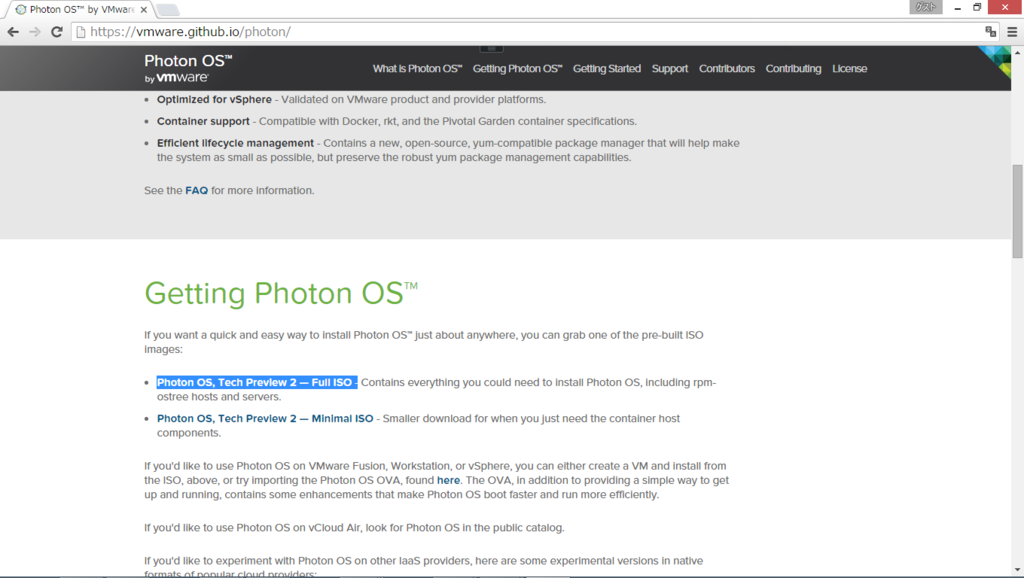
VMware Github から[Photon OS, Tech Preview 2 Full ISO]をダウンロードします。
次のサイトを参考に仮想マシンを作成し、ダウンロードしたイメージをマウントし起動します。
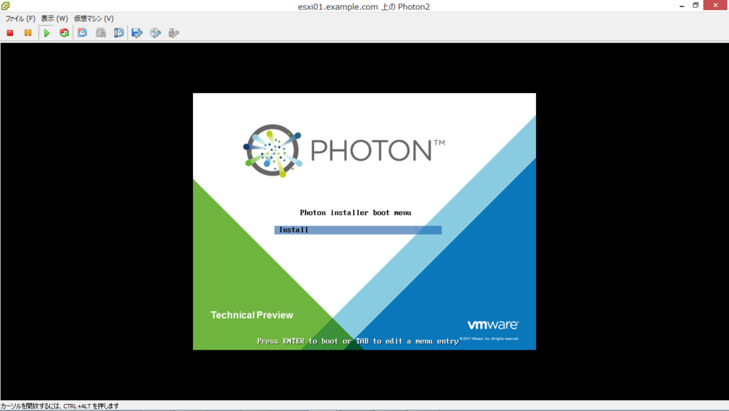
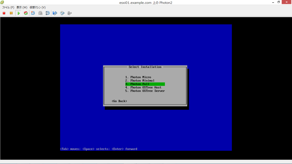
今回は、Photon Full OS (All) を選択します。
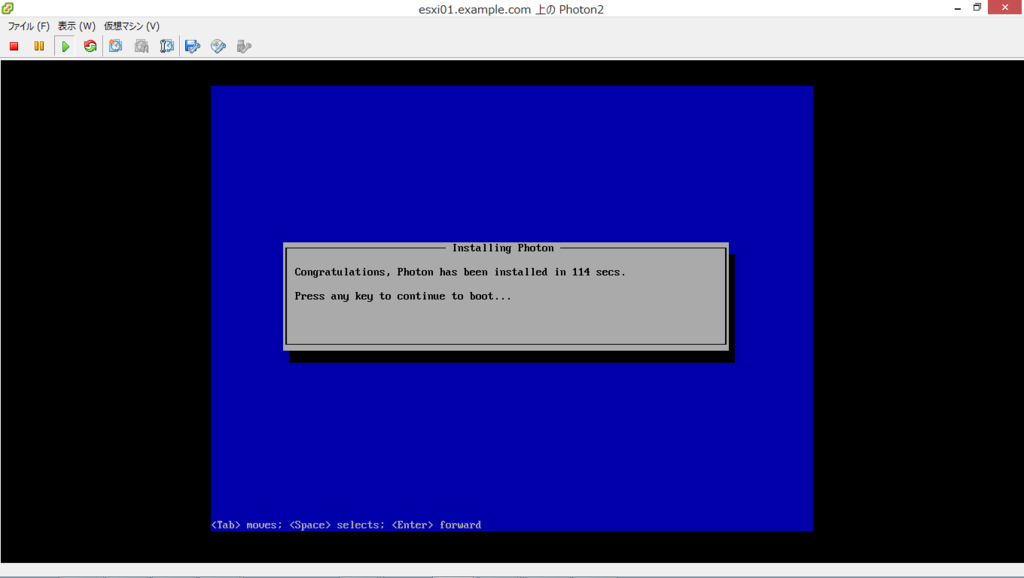
再起動後、インストール完了です。
Photon Linux の環境確認
今回インストールした Photon Linux のカーネルバージョンは、以下のとおりです。
# uname -a
Linux photon 4.0.9 #1-photon SMP Thu Aug 20 19:57:53 UTC 2015 x86_64 GNU/Linux
Photon Linux のディストリビューションバージョンは、以下のとおりです。
# cat /etc/lsb-release
DISTRIB_ID="VMware Photon"
DISTRIB_RELEASE="1.0 TP2"
DISTRIB_CODENAME=Photon
DISTRIB_DESCRIPTION="VMware Photon 1.0 TP2"
Docker のバージョンは、以下のとおりです。
> rpm -q docker
docker-1.8.1-1.ph1tp2.x86_64
Photon への SSH ログイン
root ユーザでの SSH ログインを許可します。*1
# vi /etc/ssh/sshd_config
# 134 行目あたりにある、「PermitRootLogin」を「yes」に変更します。
> PermitRootLogin yes
sshd を再起動します。
# systemctl restart sshd.service
Docker の起動
以下のコマンドで、Docker のサービスを開始します。
# systemctl start docker
# systemctl enable docker
Docker イメージのダウンロード
Docker イメージは、コンテナを実行するために必要なアーカイブ*2と、コンテナのメタ情報を持ちます。
多くのベースイメージは Docker Hub Registry で公開されているので、そこからダウンロードするのが一般的です。イメージのダウンロードは、docker pull コマンドを実行します。
(書式)
# docker pull {イメージ名}:{タグ名}
初期設定では、Docker レジストリとして「Docker Hub Registry」にアクセスするようになっています。
今回の例では、Ubuntu Linux Dockerイメージの最新版をダウンロードします。*3
# docker pull ubuntu
以下のコマンドで、ダウンロードした Docker イメージの一覧を確認します。
# docker images
REPOSITORY          TAG                 IMAGE ID            CREATED             VIRTUAL SIZE
ubuntu              latest              d55e68e6cc9c        3 weeks ago         187.9 MB
Docker コンテナの作成・実行
docker run コマンドで、コンテナの新規作成と実行の両方を行います。
(書式)
# docker run [オプション] [--name {コンテナ名}] {イメージ名}[:{タグ名}] [コンテナで実行するコマンド] [引数]
主なオプション
- 「-d」:バックグラウンドで実行する。(Web サーバー等、常時実行するコンテナで指定)
- 「-i」:コンテナの標準入力を開く。(/bin/bashなどでコンテナを操作する際に指定)
- 「-t」:tty(端末デバイス)を確保する。(/bin/bashなどでコンテナを操作する際に指定)
- 「-p{ホストのポート番号}:{コンテナのポート番号}」:Docker のホストとポートマッピングを構成
今回の例では、Ubuntu イメージからコンテナ「web01」を作成、端末を開き bash を実行します。
# docker run -it --name web01 ubuntu /bin/bash
root@ef408ef16c7a:/#
コンテナで bash が実行され、プロンプトが表示されます。
一瞬で新規作成~起動まで完了し、コンテナ内で任意の操作ができます。
Web サーバーの「nginx」をコンテナにインストールします。
# apt-get install -y nginx
curl を使用して確認します。
# curl localhost
<!DOCTYPE html>
<html>
<head>
<...snip...>
確認が完了したら[Ctrl]+[d]キーで bash プロセスを終了します。
プロセスの終了とコンテナの停止は連動するため、この時点でコンテナ「web01」は停止状態になります。
端末を再度開く場合は、プロセスを起動し docker attach コマンドを使用します。
# docker start web01
# docker attach web01
Docker コンテナの確認
Docker コンテナの一覧は、docker ps コマンドで確認します。
(書式)
# docker ps [-a]
docker ps コマンドでは実行中のコンテナのみ表示されますが、「-a」オプションを付加すると、停止中のコンテナも表示されます。
# docker ps -a
CONTAINER ID        IMAGE               COMMAND                  CREATED             STATUS                      PORTS               NAMES
ef408ef16c7a        ubuntu              "/bin/bash"              10 hours ago        Exited (0) 7 minutes ago                        web01
STATUS で「Up」は実行中、「Exit」は停止を示します。
Docker イメージの作成
上記で作成したコンテナ(web01)から、新しいイメージ(ubuntu_template)を作成してみます。
(書式)
# docker commit {コンテナ名}|{コンテナID} [{ユーザー名}/]{イメージ名}
# docker commit web01 user01/ubuntu_template
以下のコマンドで、作成した Docker イメージの一覧を確認します。
# docker images
REPOSITORY               TAG                 IMAGE ID            CREATED             VIRTUAL SIZE
user01/ubuntu_template   latest              e1f421fdefaf        5 seconds ago       216.5 MB
ubuntu                   latest              d55e68e6cc9c        3 weeks ago         187.9 MB
Docker コンテナのバックグラウンド実行
作成したイメージには、nginx が含まれているので、こちらからコンテナを作成、実行してみます。
# docker run -d -p 80:80 --name web02 user01/ubuntu_template /usr/sbin/nginx -g 'daemon off;' -c /etc/nginx/nginx.conf
7f5b4a545ba47c356148b78898d74342bd56249bc4d71938648a79279c50c10f
80番ポートを Listen しバックグラウンドで実行するようにオプションを指定します。
バックグラウンドで実行しているため、docker ps コマンドの-aオプションなしでも表示されます。
# docker ps
CONTAINER ID        IMAGE                    COMMAND                  CREATED              STATUS              PORTS                NAMES
7f5b4a545ba4        user01/ubuntu_template   "/usr/sbin/nginx -g '"   About a minute ago   Up About a minute   0.0.0.0:80->80/tcp   web02
Docker コンテナのの停止
実行中の Docker コンテナは、docker stop で停止します。
(書式)
# docker stop {コンテナ名}|{コンテナID}
停止後、docker ps を実行すると表示されなくなります。
# docker stop web02
web02
# docker ps
CONTAINER ID        IMAGE               COMMAND             CREATED             STATUS              PORTS               NAMES
Docker コンテナのの削除
Docker コンテナは docker rm、Docker イメージは docker rmi で削除します。
(書式)
# docker rm {コンテナ名}|{コンテナID}
# docker rmi {イメージ名}|{イメージID}
今回作成した Docker コンテナを削除します。
# docker rm web01
# docker rm web02
次に Docker イメージを削除します。
# docker rmi user01/ubuntu_template
Untagged: user01/ubuntu_template:latest
Deleted: e1f421fdefaf4c60018ccd3fbec43483ec8c6d07d3232d8c67293878e5422e6f
参考サイト:
https://communities.vmware.com/people/gowatana/blog
http://blog.amedama.jp/entry/2015/09/24/222040
http://www.atmarkit.co.jp/ait/articles/1405/16/news032.html
http://www.atmarkit.co.jp/ait/articles/1406/10/news031_3.html
以上
Cisco ASA のポータルページ無効化
Cisco ASA で WebVPN を使用時、ブラウザで ASA のアドレスにアクセスすると以下のようなポータルサイトが表示されます。

このポータルサイトを無効化するには、以下のコマンドを実行します。
ciscoasa# conf t
ciscoasa(config)# webvpn
ciscoasa(config-webvpn)# portal-access-rule 1 deny code 403 any
ciscoasa(config-webvpn)# end
ciscoasa# sh run web
以上