Windows Server Backup を使用した vCenter のバックアップ
Windows Server Backup を使用して、vCenter Server のバックアップが可能か、検証してみました。
結果は、問題なくリストア可能でしたが、簡易環境での結果なので、参考程度としてください。
検証環境
- Windows Server 2008R2 に、vCenter Server5.0 をインストールし、ESXi5.0 を登録する。
- ESXi 上にゲスト:Windows7 を、作成する。仮想ディスクは、データストア(NFS)に配置する。
- 分散スイッチで、仮想マシンのポートグループ(dvPortGroup)を作成し、ゲストに適用する。
検証方法
- Windows Server Backup を使用し、OS 全体のバックアップを作成する。
- vCenter Server5.0 及び、SQL Server 2008R2 をアンインストールする。
- Windows Server Backup で、リストアを行い、vCenter が復旧可能か確認する。
vCenter 及び SQL サービス停止
VMware VirtualCenter Server サービスを停止します。
> net stop "VMware VirtualCenter Server"
次のサービスは VMware VirtualCenter Server サービスに依存しています。
VMware VirtualCenter Server サービスを停止すると、これらのサービスも停止されます。

   VMware VirtualCenter Management Webservices

この操作を続行しますか? (Y/N) [N]: y
VMware VirtualCenter Server サービスが停止している事を確認します。
> net start | findstr -i VirtualCenter
VMwareVCMSDS サービスを停止します。
> net stop "VMwareVCMSDS"
VMwareVCMSDS サービスが停止している事を確認します。
> net start | findstr -i VMwareVCMSDS
SQL Server (VIM_SQLEXP)サービスを停止します。
> net stop "SQL Server (VIM_SQLEXP)"
SQL Server (VIM_SQLEXP)サービスが停止している事を確認します。
> net start | findstr -i (VIM_SQLEXP)
Inventory Service の DB バックアップ
万が一に備えて、以下の手順で、Inventory Service の DB のバックアップを取得します。*1
> cd C:\Program Files\VMware\Infrastructure\Inventory Service\scripts
> backup.bat -file backuptest
Inventory Service の DB のバックアップが作成された事を確認します。
> dir | findstr backuptest
2014/07/15  13:39         9,487,974 backuptest
SSL 証明書ファイルのバックアップ
万が一に備えて、SSL 証明書ファイルのバックアップを取得します。*2
"%ALLUSERSPROFILE%\VMWare\VMware VirtualCenter" 配下の全てのファイル
Windows Server Backup による全体バックアップ
Windows Server Backup は、「機能の追加」からインストールします。

インストール完了後、「管理ツール」から起動します。

「操作」タブから、「バックアップ(1回限り)」を実行します。

「次へ」をクリックします。

「サーバー全体」を選択し、「次へ」をクリックします。

「ローカルドライブ」を選択し、「次へ」をクリックします。

バックアップ先のボリュームを指定して、「次へ」をクリックします。*3

「OK」をクリックします。

「バックアップ」をクリックします。

バックアップが完了後、「閉じる」をクリックします。

バックアップをテストするため、vCenter と SQL サービスをアンインストールします。
Windows Server Backup による全体リストア
サーバーを、Windows Server 2008R2 のインストーラーから起動し、「次へ」をクリックします。

「コンピュータを修復する」をクリックします。

「以前に作成したシステムイメージを使用して・・」をチェックし、「次へ」をクリックします。

「利用可能なシステムイメージのうち最新のものを使用する」をチェックし「次へ」をクリックします。

「次へ」をクリックします。

「完了」をクリックします。

「はい」をクリックします。

vCenter サーバーが正常に復旧する事を確認できました。

また、検証中、ゲストへの影響がない事を確認できました。

Data Protection SnapMirror について
Data Protection SnapMirror とは
従来のデータ保護を目的とした、クラスタ内/クラスタ間のミラーリング機能になります。
クラスタ内 SnapMirror
- Cluster Network を使用して、ローカルクラスタ上で、SnapMirror を行う。
- ターゲットボリュームは、Source と同じ SVM でも、異なる SVM でも良い。
クラスタ間 SnapMirror
- 異なるクラスタに存在するボリューム間で、SnapMirror を行う。
- クラスタ間の Intercluster LIF を使用する。
設定例
Source 側の設定
Cluster 間通信用の VLAN を定義します。
cluster1::> network port vlan create -node cluster1-01 -vlan-name a0a-99
cluster1::> network port vlan create -node cluster1-02 -vlan-name a0a-99
Cluster 間通信用の VLAN が定義された事を確認します。
cluster1::> network port vlan show
                 Network Network
Node   VLAN Name Port    VLAN ID  MAC Address
------ --------- ------- -------- -----------------
cluster1-01
       a0a-10    a0a     10       02:0c:29:c4:aa:e4
       a0a-20    a0a     20       02:0c:29:c4:aa:e4
       a0a-30    a0a     30       02:0c:29:c4:aa:e4
       a0a-99    a0a     99       02:0c:29:c4:aa:e4
cluster1-02
       a0a-10    a0a     10       02:0c:29:c0:8c:8a
       a0a-20    a0a     20       02:0c:29:c0:8c:8a
       a0a-30    a0a     30       02:0c:29:c0:8c:8a
       a0a-99    a0a     99       02:0c:29:c0:8c:8a
8 entries were displayed.
Cluster 間通信用の FailoverGroup を定義します。
cluster1::> network interface failover-groups create -failover-group failovergroup -node cluster1-01 -port a0a-99
cluster1::> network interface failover-groups create -failover-group failovergroup -node cluster1-02 -port a0a-99
Cluster 間通信用の FailoverGroup を定義された事を確認します。
cluster1::> network interface failover-groups show
Failover
Group               Node              Port
------------------- ----------------- ----------
clusterwide
                    cluster1-01       a0a
                    cluster1-01       e0c
                    cluster1-02       a0a
                    cluster1-02       e0c
failovergroup
                    cluster1-01       a0a-10
                    cluster1-01       a0a-99
                    cluster1-02       a0a-10
                    cluster1-02       a0a-99
8 entries were displayed.
Cluster 間通信用の LIF を作成します。
cluster1::> network interface create -vserver cluster1-01 -lif lif-cluster01 -role intercluster -home-node cluster1-01 -home-port a0a-99 -address 172.16.99.11 -netmask 255.255.255.0
cluster1::> network interface create -vserver cluster1-02 -lif lif-cluster02 -role intercluster -home-node cluster1-02 -home-port a0a-99 -address 172.16.99.12 -netmask 255.255.255.0
Cluster 間通信用の LIF が作成されている事を確認します。
cluster1::> network interface show lif-cluster01,lif-cluster02
            Logical    Status     Network            Current       Current Is
Vserver     Interface  Admin/Oper Address/Mask       Node          Port    Home
----------- ---------- ---------- ------------------ ------------- ------- ----
cluster1-01
            lif-cluster01
                         up/up    172.16.99.11/24    cluster1-01   a0a-99  true
cluster1-02
            lif-cluster02
                         up/up    172.16.99.12/24    cluster1-02   a0a-99  true
2 entries were displayed.
Destination 側の設定
インターフェースグループを作成します。
cluster2::>  network port ifgrp create -node cluster2-01 -ifgrp a0a -distr-func ip -mode multimode
cluster2::>  network port ifgrp create -node cluster2-02 -ifgrp a0a -distr-func ip -mode multimode
インターフェースグループが作成された事を確認します。
cluster2::> network port ifgrp show
         Port       Distribution                   Active
Node     IfGrp      Function     MAC Address       Ports   Ports
-------- ---------- ------------ ----------------- ------- -------------------
cluster2-01
         a0a        ip           02:0c:29:af:99:db none    -
cluster2-02
         a0a        ip           02:0c:29:96:f8:e7 none    -
2 entries were displayed.
インターフェースグループにポートを追加します。
cluster2::> network port ifgrp add-port -node cluster2-01 -ifgrp a0a -port e0d
cluster2::> network port ifgrp add-port -node cluster2-02 -ifgrp a0a -port e0d
インターフェースグループにポートが追加された事を確認します。
cluster2::> network port ifgrp show
         Port       Distribution                   Active
Node     IfGrp      Function     MAC Address       Ports   Ports
-------- ---------- ------------ ----------------- ------- -------------------
cluster2-01
         a0a        ip           02:0c:29:af:99:db full    e0d
cluster2-02
         a0a        ip           02:0c:29:96:f8:e7 full    e0d
2 entries were displayed.
Cluster 間通信用の VLAN を定義します。
cluster2::> network port vlan create -node cluster2-01 -vlan-name a0a-99
cluster2::> network port vlan create -node cluster2-02 -vlan-name a0a-99
Cluster 間通信用の VLAN が定義された事を確認します。
cluster2::> network port vlan show
                 Network Network
Node   VLAN Name Port    VLAN ID  MAC Address
------ --------- ------- -------- -----------------
cluster2-01
       a0a-99    a0a     99       02:0c:29:af:99:db
cluster2-02
       a0a-99    a0a     99       02:0c:29:96:f8:e7
2 entries were displayed.
Cluster 間通信用の FailoverGroup を定義します。
cluster2::> network interface failover-groups create -failover-group failovergroup -node cluster2-01 -port a0a-99
cluster2::> network interface failover-groups create -failover-group failovergroup -node cluster2-02 -port a0a-99
Cluster 間通信用の FailoverGroup を定義された事を確認します。
cluster2::> network interface failover-groups show
Failover
Group               Node              Port
------------------- ----------------- ----------
clusterwide
                    cluster2-02       a0a
                    cluster2-02       e0c
                    cluster2-01       a0a
                    cluster2-01       e0c
failovergroup
                    cluster2-02       a0a-99
                    cluster2-01       a0a-99
6 entries were displayed.
vserver setup コマンドで SVM を作成します。
cluster2::> vserver setup
Welcome to the Vserver Setup Wizard, which will lead you through
the steps to create a virtual storage server that serves data to clients.

You can enter the following commands at any time:
"help" or "?" if you want to have a question clarified,
"back" if you want to change your answers to previous questions, and
"exit" if you want to quit the Vserver Setup Wizard. Any changes
you made before typing "exit" will be applied.

You can restart the Vserver Setup Wizard by typing "vserver setup". To accept a default
or omit a question, do not enter a value.

Vserver Setup wizard creates and configures only data Vservers.
If you want to create a Vserver with Infinite Volume use the vserver create command.

Step 1. Create a Vserver.
You can type "back", "exit", or "help" at any question.

Enter the Vserver name: bsvm-01
Choose the Vserver data protocols to be configured {nfs, cifs, fcp, iscsi, ndmp}:  nfs, cifs, fcp, iscsi, ndmp
Choose the Vserver client services to be configured {ldap, nis, dns}: dns
Enter the Vserver's root volume aggregate [aggr1]: aggr1
Enter the Vserver language setting, or "help" to see all languages [C.UTF-8]: C
Enter the Vserver root volume's security style {mixed, ntfs, unix} [unix]: unix
Vserver creation might take some time to finish....

Vserver bsvm-01 with language set to C created.  The permitted protocols are nfs,cifs,fcp,iscsi,ndmp.

Step 2: Create a data volume
You can type "back", "exit", or "help" at any question.

Do you want to create a data volume? {yes, no} [yes]: no

Step 3: Create a logical interface.
You can type "back", "exit", or "help" at any question.

Do you want to create a logical interface? {yes, no} [yes]: no

Step 4: Configure DNS (Domain Name Service).
You can type "back", "exit", or "help" at any question.

Do you want to configure DNS? {yes, no} [yes]: no
Error: Failed to create NFS. Reason: You do not have a valid license for "NFS". Reason: Package "NFS" is not licensed in the cluster.

Step 5: Configure NFS.
You can type "back", "exit", or "help" at any question.

Step 6: Configure CIFS.
You can type "back", "exit", or "help" at any question.

Do you want to configure CIFS? {yes, no} [yes]: no

Step 7: Configure iSCSI.
You can type "back", "exit", or "help" at any question.

Do you want to configure iSCSI? {yes, no} [yes]: no

Step 8: Configure FCP.
You can type "back", "exit", or "help" at any question.

Do you want to configure FCP? {yes, no} [yes]: no

Vserver bsvm-01 has been configured successfully.
Cluster 間通信用の LIF を作成します。
cluster2::> network interface create -vserver cluster2-01 -lif lif-cluster01 -role intercluster -home-node cluster2-01 -home-port a0a-99 -address 172.16.99.21 -netmask 255.255.255.0
cluster2::> network interface create -vserver cluster2-02 -lif lif-cluster02 -role intercluster -home-node cluster2-02 -home-port a0a-99 -address 172.16.99.22 -netmask 255.255.255.0
Cluster 間通信用の LIF が作成されている事を確認します。
cluster2::> network interface show lif-cluster01,lif-cluster02
            Logical    Status     Network            Current       Current Is
Vserver     Interface  Admin/Oper Address/Mask       Node          Port    Home
----------- ---------- ---------- ------------------ ------------- ------- ----
cluster2-01
            lif-cluster01
                         up/up    172.16.99.21/24    cluster2-01   a0a-99  true
cluster2-02
            lif-cluster02
                         up/up    172.16.99.22/24    cluster2-02   a0a-99  true
2 entries were displayed.
Cluster Peer を作成します。
cluster2::> cluster peer create -peer-addrs 172.16.99.11,172.16.99.12 -username admin
Remote Password:
Cluster Peer が作成されている事を確認します。
cluster2::> cluster peer show -instance

            Peer Cluster Name: cluster1
Remote Intercluster Addresses: 172.16.99.11, 172.16.99.12
                 Availability: Available
          Remote Cluster Name: cluster1
          Active IP Addresses: 172.16.99.11, 172.16.99.12
        Cluster Serial Number: 1-80-000008
Vserver Peer を作成します。
cluster2::> vserver peer create -vserver bsvm-01 -peer-vserver svm-01 -applications snapmirror -peer-cluster cluster1
Vserver Peer が作成されている事を確認します。※この時点では、まだ承認されていません。
cluster2::> vserver peer show
            Peer        Peer
Vserver     Vserver     State
----------- ----------- ------------
bsvm-01     svm-01      initiated
Source 側で、destination 側の Vserver Peer を承認します。
cluster1::> vserver peer accept -vserver svm-01 -peer-vserver bsvm-01
Vserver Peer が承認されている事を確認します
cluster2::> vserver peer show
            Peer        Peer
Vserver     Vserver     State
----------- ----------- ------------
bsvm-01     svm-01      peered
SnapMirror 送信先の Volume を作成します。
cluster2::> volume create -vserver bsvm-01 -volume rootvol_is -aggregate aggr1 -type DP
送信先の Volume が作成された事を確認します。
cluster2::> volume show -volume rootvol_is
Vserver   Volume       Aggregate    State      Type       Size  Available Used%
--------- ------------ ------------ ---------- ---- ---------- ---------- -----
bsvm-01   rootvol_is   aggr1        online     DP         20MB    19.89MB    0%
InterCluster SnapMirror を作成します。
cluster2::> snapmirror create -source-path cluster1://svm-01/rootvol bsvm-01:rootvol_is -type DP
InterCluster SnapMirror が作成された事を確認します。
cluster2::> snapmirror show
                                                                       Progress
Source            Destination  Mirror  Relationship  Total             Last
Path        Type  Path         State   Status        Progress  Healthy Updated
----------- ---- ------------ ------- -------------- --------- ------- --------
svm-01:rootvol
            DP   bsvm-01:rootvol_is
                              Uninitialized
                                      Idle           -         true    -
InterCluste SnapMirror の Initialize を行います。
cluster2::> snapmirror initialize -source-path cluster1://svm-01/rootvol bsvm-01:rootvol_is
Initialize が完了した事を確認します。
cluster1::> snapmirror show
                                                                       Progress
Source            Destination  Mirror  Relationship  Total             Last
Path        Type  Path         State   Status        Progress  Healthy Updated
----------- ---- ------------ ------- -------------- --------- ------- --------
svm-01:rootvol
            DP   bsvm-01:rootvol_is
                              Snapmirrored
                                      Idle           -         true    -
以上
Load Sharing SnapMirror について
Load Sharing SnapMirror とは
クアライアントからの Read(読み取り)要求を分散して、スループットを向上させる機能になります。
具体的には、Root を含む任意の Volume のコピー(読み取り専用)を、マスターとは別の Aggregate に作成し、クライアントからの Read 要求を分散します。*1書き込みについては、マスターにのみ行われ、分散されません。
注意点
マスターからコピーに対し、リアルタイムミラーリングが行われないため、マスターで更新されたデータを、読み取れるようにするには、LS ミラーをアップデートする必要があります。これに関連して、Root volume をコピーした際、Root 配下に新たな Volume を作成しても、(LS ミラーをアップデートするまで、コピー先の、Junction Path が更新されないため)当該 Volume にアクセスできない事に注意してください。
設定例
SnapMirror 送信先の Volume を作成します。
cluster1::> volume create -vserver svm-01 -volume rootvol_ls -aggregate aggr2 -type DP
送信先の Volume が作成された事を確認します。
cluster1::> volume show -volume rootvol_ls
Vserver   Volume       Aggregate    State      Type       Size  Available Used%
--------- ------------ ------------ ---------- ---- ---------- ---------- -----
svm-01    rootvol_ls   aggr2        online     DP         20MB    19.89MB    0%
LS SnapMirror を作成します。
cluster1::> snapmirror create -source-path svm-01:rootvol -destination-path svm-01:rootvol_ls -type LS
LS SnapMirror が作成された事を確認します。
cluster1::> snapmirror show
                                                                       Progress
Source            Destination  Mirror  Relationship  Total             Last
Path        Type  Path         State   Status        Progress  Healthy Updated
----------- ---- ------------ ------- -------------- --------- ------- --------
cluster1://svm-01/rootvol
            LS   cluster1://svm-01/rootvol_ls
                              Uninitialized
                                      Idle           -         -       -
LS SnapMirror の Initialize を行います。
cluster1::> snapmirror initialize-ls-set -source-path svm-01:rootvol
Initialize が完了した事を確認します。
cluster1::> snapmirror show
                                                                       Progress
Source            Destination  Mirror  Relationship  Total             Last
Path        Type  Path         State   Status        Progress  Healthy Updated
----------- ---- ------------ ------- -------------- --------- ------- --------
cluster1://svm-01/rootvol
            LS   cluster1://svm-01/rootvol_ls
                              Snapmirrored
                                      Idle           -         true    -
Volume サイズが、マスターと同様となっている事を確認します。
cluster1::> volume show -volume rootvol,rootvol_ls
Vserver   Volume       Aggregate    State      Type       Size  Available Used%
--------- ------------ ------------ ---------- ---- ---------- ---------- -----
svm-01    rootvol      aggr1        online     RW          2GB     1.90GB    5%
svm-01    rootvol_ls   aggr2        online     LS          2GB     1.90GB    5%
2 entries were displayed.
新規の Volume を作成すると、下記のとおり、留意事項が通知されます。
cluster1::> volume create -vserver svm-01 -volume vol_nfs02 -aggregate aggr1 -size 1g -security-style unix -space-guarantee none -junction-path /vol_nfs02
[Job 82] Job succeeded: Successful

Notice: Volume vol_nfs02 now has a mount point from volume rootvol.  The load sharing (LS) mirrors of volume
        rootvol have no replication schedule.  Volume vol_nfs02 will not be visible in the global namespace until
        the LS mirrors of volume rootvol have been updated.
        現状、LS SnapMirror スケジュールが設定されていないため、アップデートされるまで、クライントからアクセスできません。
LS SnapMirror をアップデートします。
cluster1::> snapmirror update-ls-set -source-path svm-01:rootvol
LS SnapMirror がアップデートされた事を確認します。
cluster1::> snapmirror show
                                                                       Progress
Source            Destination  Mirror  Relationship  Total             Last
Path        Type  Path         State   Status        Progress  Healthy Updated
----------- ---- ------------ ------- -------------- --------- ------- --------
cluster1://svm-01/rootvol
            LS   cluster1://svm-01/rootvol_ls
                              Snapmirrored
                                      Idle           -         true    -
LS SnapMirror のスケジュールを作成します。
cluster1::> job schedule cron create -name sched01 -hour 1 -minute 0
LS SnapMirror にスケジュールを適用します。
cluster1::> snapmirror modify -destination-path svm-01:rootvol_ls -schedule sched01
LS SnapMirror にスケジュールが設定されている事を確認します。
cluster1::> snapmirror show -fields schedule
source-path               destination-path             schedule
------------------------- ---------------------------- --------
cluster1://svm-01/rootvol cluster1://svm-01/rootvol_ls sched01
以上
*1:クライアントからの Read 要求は、全てコピーされた Volume に向けられます。
Clustered ONTAP の基本操作について
Aggregate の操作
Raid サイズ、Disk 数を指定して Aggregate を作成します。
cluster1::> storage aggregate create -aggregate aggr1 -raidtype raid_dp -diskcount 5 -nodes cluster1-01 -maxraidsize 22
aggr1 が作成されている事を確認します。
cluster1::> storage aggregate show
Aggregate     Size Available Used% State   #Vols  Nodes            RAID Status
--------- -------- --------- ----- ------- ------ ---------------- ------------
aggr0       5.27GB    4.44GB   16% online       1 cluster1-01      raid_dp,
                                                                   normal
aggr0_cluster1_02_0
             900MB   43.54MB   95% online       1 cluster1-02      raid_dp,
                                                                   normal
aggr1       2.64GB    2.64GB    0% online       0 cluster1-01      raid_dp,
                                                                   normal
3 entries were displayed.
disk が aggr1 にアサインされている事を確認します。
cluster1::> disk show -aggregate aggr1
                     Usable           Container
Disk                   Size Shelf Bay Type        Position   Aggregate Owner
---------------- ---------- ----- --- ----------- ---------- --------- --------
cluster1-01:v4.21    1020MB     -   - aggregate   dparity    aggr1     cluster1-01
cluster1-01:v4.22    1020MB     -   - aggregate   data       aggr1     cluster1-01
cluster1-01:v4.24    1020MB     -   - aggregate   data       aggr1     cluster1-01
cluster1-01:v5.19    1020MB     -   - aggregate   parity     aggr1     cluster1-01
cluster1-01:v5.20    1020MB     -   - aggregate   data       aggr1     cluster1-01
5 entries were displayed.
aggr1 に disk を1本追加します。
cluster1::> storage aggregate add-disks -aggregate aggr1 -disklist cluster1-01:v4.25
disk が追加され、aggr1 の容量が増加している事を確認する。
cluster1::> storage aggregate show
Aggregate     Size Available Used% State   #Vols  Nodes            RAID Status
--------- -------- --------- ----- ------- ------ ---------------- ------------
aggr0       5.27GB    4.44GB   16% online       1 cluster1-01      raid_dp,
                                                                   normal
aggr0_cluster1_02_0
             900MB   43.54MB   95% online       1 cluster1-02      raid_dp,
                                                                   normal
aggr1       3.52GB    3.51GB    0% online       0 cluster1-01      raid_dp,
                                                                   normal
3 entries were displayed.
disk(cluster1-01:v4.25)が aggr1 にアサインされている事を確認します。
cluster1::> disk show -aggregate aggr1
                     Usable           Container
Disk                   Size Shelf Bay Type        Position   Aggregate Owner
---------------- ---------- ----- --- ----------- ---------- --------- --------
cluster1-01:v4.21    1020MB     -   - aggregate   dparity    aggr1     cluster1-01
cluster1-01:v4.22    1020MB     -   - aggregate   data       aggr1     cluster1-01
cluster1-01:v4.24    1020MB     -   - aggregate   data       aggr1     cluster1-01
cluster1-01:v4.25    1020MB     -   - aggregate   data       aggr1     cluster1-01
cluster1-01:v5.19    1020MB     -   - aggregate   parity     aggr1     cluster1-01
cluster1-01:v5.20    1020MB     -   - aggregate   data       aggr1     cluster1-01
6 entries were displayed.
インターフェースグループの作成
インターフェースグループを作成します。
cluster1::> network port ifgrp create -node cluster1-01 -ifgrp a0a -distr-func ip -mode multimode
cluster1::> network port ifgrp create -node cluster1-02 -ifgrp a0a -distr-func ip -mode multimode
インターフェースグループが作成された事を確認します。
cluster1::> network port ifgrp show
         Port       Distribution                   Active
Node     IfGrp      Function     MAC Address       Ports   Ports
-------- ---------- ------------ ----------------- ------- -------------------
cluster1-01
         a0a        ip           02:0c:29:c4:aa:e4 none    -
cluster1-02
         a0a        ip           02:0c:29:c0:8c:8a none    -
インターフェースグループにポートを追加します。
cluster1::> network port ifgrp add-port -node cluster1-01 -ifgrp a0a -port e0d
cluster1::> network port ifgrp add-port -node cluster1-02 -ifgrp a0a -port e0d
インターフェースグループにポートが追加された事を確認します。
cluster1::> network port ifgrp show
         Port       Distribution                   Active
Node     IfGrp      Function     MAC Address       Ports   Ports
-------- ---------- ------------ ----------------- ------- -------------------
cluster1-01
         a0a        ip           02:0c:29:c4:aa:e4 full    e0d
cluster1-02
         a0a        ip           02:0c:29:c0:8c:8a full    e0d
2 entries were displayed.
VLAN 作成
VLAN を作成します。
cluster1::> network port vlan create -node cluster1-01 -vlan-name a0a-10
cluster1::> network port vlan create -node cluster1-02 -vlan-name a0a-10
VLAN が作成された事を確認します。
cluster1::> network port vlan show
                 Network Network
Node   VLAN Name Port    VLAN ID  MAC Address
------ --------- ------- -------- -----------------
cluster1-01
       a0a-10    a0a     10       02:0c:29:c4:aa:e4
cluster1-02
       a0a-10    a0a     10       02:0c:29:c0:8c:8a
2 entries were displayed.
フェイルオーバーグループ作成
フェイルオーバーグループを作成します。
cluster1::> network interface failover-groups create -failover-group failovergroup -node cluster1-01 -port a0a-10
cluster1::> network interface failover-groups create -failover-group failovergroup -node cluster1-02 -port a0a-10
フェイルオーバーグループが作成された事を確認します。
cluster1::> network interface failover-groups show
Failover
Group               Node              Port
------------------- ----------------- ----------
clusterwide
                    cluster1-01       a0a
                    cluster1-01       e0c
                    cluster1-02       a0a
                    cluster1-02       e0c
failovergroup
                    cluster1-01       a0a-10
                    cluster1-02       a0a-10
6 entries were displayed.
SVM(Server Virtual Machine)作成
vserver setup コマンドで SVM を作成します。
cluster1::> vserver setup
Welcome to the Vserver Setup Wizard, which will lead you through
the steps to create a virtual storage server that serves data to clients.

You can enter the following commands at any time:
"help" or "?" if you want to have a question clarified,
"back" if you want to change your answers to previous questions, and
"exit" if you want to quit the Vserver Setup Wizard. Any changes
you made before typing "exit" will be applied.

You can restart the Vserver Setup Wizard by typing "vserver setup". To accept a default
or omit a question, do not enter a value.

Vserver Setup wizard creates and configures only data Vservers.
If you want to create a Vserver with Infinite Volume use the vserver create command.

Step 1. Create a Vserver.
You can type "back", "exit", or "help" at any question.

Enter the Vserver name: svm-01
Choose the Vserver data protocols to be configured {nfs, cifs, fcp, iscsi, ndmp}: nfs, cifs, fcp, iscsi, ndmp
Choose the Vserver client services to be configured {ldap, nis, dns}: dns
Enter the Vserver's root volume aggregate [aggr1]: aggr1
Enter the Vserver language setting, or "help" to see all languages [C]:
Enter the Vserver root volume's security style {mixed, ntfs, unix} [unix]:
Vserver creation might take some time to finish....

Vserver svm-01 with language set to C created.  The permitted protocols are nfs,cifs,fcp,iscsi,ndmp.

Step 2: Create a data volume
You can type "back", "exit", or "help" at any question.

Do you want to create a data volume? {yes, no} [yes]: no

Step 3: Create a logical interface.
You can type "back", "exit", or "help" at any question.

Do you want to create a logical interface? {yes, no} [yes]: no

Step 4: Configure DNS (Domain Name Service).
You can type "back", "exit", or "help" at any question.

Do you want to configure DNS? {yes, no} [yes]: no
Error: Failed to create NFS. Reason: You do not have a valid license for "NFS". Reason: Package "NFS" is not licensed in the cluster.

Step 5: Configure NFS.
You can type "back", "exit", or "help" at any question.

Step 6: Configure CIFS.
You can type "back", "exit", or "help" at any question.

Do you want to configure CIFS? {yes, no} [yes]: no

Step 7: Configure iSCSI.
You can type "back", "exit", or "help" at any question.

Do you want to configure iSCSI? {yes, no} [yes]: no

Step 8: Configure FCP.
You can type "back", "exit", or "help" at any question.

Do you want to configure FCP? {yes, no} [yes]: no

Vserver svm-01 has been configured successfully.
SVM が作成されている事を確認します。
cluster1::> vserver show
                    Admin     Root                  Name    Name
Vserver     Type    State     Volume     Aggregate  Service Mapping
----------- ------- --------- ---------- ---------- ------- -------
cluster1    admin   -         -          -          -       -
cluster1-01 node    -         -          -          -       -
cluster1-02 node    -         -          -          -       -
svm-01      data    running   rootvol    aggr1      file    file
4 entries were displayed.
LIF(Logical Interface) 作成
- role について
- クラスタネットワークで使用する LIF は、cluster を定義します。
- データ通信で使用する LIF は、data を定義します。通常、SVM 上に作成する LIF です。
- ノード管理で使用する LIF は、node-mgmt を定義します。
- Intercluster SnapMirror で使用する LIF は、intercluster を定義します。
- クラスタ管理に使用する LIF は、cluster-mgmt を定義します。
iSCSI 用の LIF を作成します。
cluster1::> network interface create -vserver svm-01 -lif lif-iscsi01 -role data -data-protocol iscsi -home-node cluster1-01 -home-port a0a-10 -address 172.16.10.11 -netmask 255.255.255.0
cluster1::> network interface create -vserver svm-01 -lif lif-iscsi02 -role data -data-protocol iscsi -home-node cluster1-02 -home-port a0a-10 -address 172.16.10.12 -netmask 255.255.255.0
iSCSI 用の LIF が作成されている事を確認します。
cluster1::> network interface show lif-iscsi01,lif-iscsi02
            Logical    Status     Network            Current       Current Is
Vserver     Interface  Admin/Oper Address/Mask       Node          Port    Home
----------- ---------- ---------- ------------------ ------------- ------- ----
svm-01
            lif-iscsi01  up/up    172.16.10.11/24    cluster1-01   a0a-10  true
            lif-iscsi02  up/up    172.16.10.12/24    cluster1-02   a0a-10  true
2 entries were displayed.
NFS 用の LIF を作成します。NFS の LIF はマイグレートが可能です。
cluster1::> network interface create -vserver svm-01 -lif lif-nfs01 -role data -data-protocol nfs -home-node cluster1-01 -home-port a0a-10 -address 172.16.20.11 -netmask 255.255.255.0 -failover-group failovergroup
cluster1::> network interface create -vserver svm-01 -lif lif-nfs02 -role data -data-protocol nfs -home-node cluster1-02 -home-port a0a-10 -address 172.16.20.12 -netmask 255.255.255.0 -failover-group failovergroup
NFS 用の LIF が作成されている事を確認します。
cluster1::> network interface show lif-nfs01,lif-nfs02
            Logical    Status     Network            Current       Current Is
Vserver     Interface  Admin/Oper Address/Mask       Node          Port    Home
----------- ---------- ---------- ------------------ ------------- ------- ----
svm-01
            lif-nfs01    up/up    172.16.20.11/24    cluster1-01   a0a-10  true
            lif-nfs02    up/up    172.16.20.12/24    cluster1-02   a0a-10  true
2 entries were displayed.
LIF の詳細情報を確認する際は、-instance オプションを使用します。
cluster1::> network interface show -lif lif-iscsi01 -instance

                    Vserver Name: svm-01
          Logical Interface Name: lif-iscsi01
                            Role: data
                   Data Protocol: iscsi
                       Home Node: cluster1-01
                       Home Port: a0a-10
                    Current Node: cluster1-01
                    Current Port: a0a-10
              Operational Status: up
                 Extended Status: -
                         Is Home: true
                 Network Address: 172.16.10.11
                         Netmask: 255.255.255.0
             Bits in the Netmask: 24
                 IPv4 Link Local: -
              Routing Group Name: d172.16.99.0/24
           Administrative Status: up
                 Failover Policy: disabled
                 Firewall Policy: data
                     Auto Revert: false
   Fully Qualified DNS Zone Name: none
         DNS Query Listen Enable: false
             Failover Group Name:
                        FCP WWPN: -
                  Address family: ipv4
                         Comment: -
LIF の設定を変更する際は、modefy コマンドを使用します。
cluster1::> network interface modify -vserver svm-01 -lif lif-iscsi01 -address 172.16.100.11
CIFS 用の LIF を作成します。
cluster1::> network interface create -vserver svm-01 -lif lif-cifs01 -role data -data-protocol cifs -home-node cluster1-01 -home-port a0a-10 -address 172.16.30.11 -netmask 255.255.255.0
cluster1::> network interface create -vserver svm-01 -lif lif-cifs02 -role data -data-protocol cifs -home-node cluster1-02 -home-port a0a-10 -address 172.16.30.12 -netmask 255.255.255.0
CIFS 用の LIF が作成されている事を確認します。
cluster1::> network interface show lif-cifs01,lif-cifs02
            Logical    Status     Network            Current       Current Is
Vserver     Interface  Admin/Oper Address/Mask       Node          Port    Home
----------- ---------- ---------- ------------------ ------------- ------- ----
svm-01
            lif-cifs01   up/up    172.16.30.11/24    cluster1-01   a0a-10  true
            lif-cifs02   up/up    172.16.30.12/24    cluster1-02   a0a-10  true
2 entries were displayed.
LIF をマイグレート*2します。
※iSCSI の LIF では、マイグレートをサポートしていません。
cluster1::> network interface migrate -vserver svm-01 -lif lif-nfs01 -dest-node cluster1-02 -dest-port a0a-10
lif-nfs01 の Home Node が cluster1-01 から cluster1-02 へ移行した事を確認します。
cluster1::> network interface show lif-nfs01,lif-nfs02
            Logical    Status     Network            Current       Current Is
Vserver     Interface  Admin/Oper Address/Mask       Node          Port    Home
----------- ---------- ---------- ------------------ ------------- ------- ----
svm-01
            lif-nfs01    up/up    172.16.20.11/24    cluster1-02   a0a-10  false
            lif-nfs02    up/up    172.16.20.12/24    cluster1-02   a0a-10  true
2 entries were displayed.
LIF をリバート*3します。
cluster1::> network interface revert -vserver svm-01 -lif lif-nfs01
lif-nfs01 の Home Node が cluster1-02 から cluster1-01 へ戻った事を確認します。
cluster1::> network interface show lif-nfs01,lif-nfs02
            Logical    Status     Network            Current       Current Is
Vserver     Interface  Admin/Oper Address/Mask       Node          Port    Home
----------- ---------- ---------- ------------------ ------------- ------- ----
svm-01
            lif-nfs01    up/up    172.16.20.11/24    cluster1-01   a0a-10  true
            lif-nfs02    up/up    172.16.20.12/24    cluster1-02   a0a-10  true
2 entries were displayed.
SVM 上の全ての LIF を Home Port に戻す際は、lif_name を指定せず * を入力します。
cluster1::> network interface revert -vserver svm-01 *
LIF に適用している VLAN の変更
VLAN-id 20 を定義します。
cluster1::> network port vlan create -node cluster1-01 -vlan-name a0a-20
cluster1::> network port vlan create -node cluster1-02 -vlan-name a0a-20
VLAN が作成された事を確認します。
cluster1::> network port vlan show
                 Network Network
Node   VLAN Name Port    VLAN ID  MAC Address
------ --------- ------- -------- -----------------
cluster1-01
       a0a-10    a0a     10       02:0c:29:c4:aa:e4
       a0a-20    a0a     20       02:0c:29:c4:aa:e4
cluster1-02
       a0a-10    a0a     10       02:0c:29:c0:8c:8a
       a0a-20    a0a     20       02:0c:29:c0:8c:8a
4 entries were displayed.
LIF(lif-nfs)の home-port を VLAN 20 に指定します。
cluster1::> network interface modify -vserver svm-01 -lif lif-nfs01 -home-node cluster1-01 -home-port a0a-20
cluster1::> network interface modify -vserver svm-01 -lif lif-nfs02 -home-node cluster1-02 -home-port a0a-20
現状は、home-port が VLAN 10 となっている事を確認します。
cluster1::> network interface show -lif lif-nfs01,lif-nfs02
            Logical    Status     Network            Current       Current Is
Vserver     Interface  Admin/Oper Address/Mask       Node          Port    Home
----------- ---------- ---------- ------------------ ------------- ------- ----
svm-01
            lif-nfs01    up/up    172.16.20.11/24    cluster1-01   a0a-10  false
            lif-nfs02    up/up    172.16.20.12/24    cluster1-02   a0a-10  false
2 entries were displayed.
home-port を VLAN20 へ移行します。
cluster1::> network interface migrate -vserver svm-01 -lif lif-nfs01 -dest-node cluster1-01 -dest-port a0a-20
cluster1::> network interface migrate -vserver svm-01 -lif lif-nfs02 -dest-node cluster1-02 -dest-port a0a-20
home-port が VLAN20 へ移行した事を確認します。
cluster1::> network interface show lif-nfs01,lif-nfs02
            Logical    Status     Network            Current       Current Is
Vserver     Interface  Admin/Oper Address/Mask       Node          Port    Home
----------- ---------- ---------- ------------------ ------------- ------- ----
svm-01
            lif-nfs01    up/up    172.16.20.11/24    cluster1-01   a0a-20  true
            lif-nfs02    up/up    172.16.20.12/24    cluster1-02   a0a-20  true
2 entries were displayed.
ルーティング設定*4
SVM-01 にデフォルトルートを設定します。
cluster1::> network routing-groups route create -vserver svm-01 -routing-group d172.16.10.0/24 -destination 0.0.0.0/0 -gateway 172.16.10.254
SVM-01 のルーティングテーブルを確認します。
cluster1::> network routing-groups route show
          Routing
Vserver   Group     Destination     Gateway         Metric
--------- --------- --------------- --------------- ------
cluster1
          c192.168.1.0/24
                    0.0.0.0/0       192.168.1.2     20
cluster1-01
          n192.168.1.0/24
                    0.0.0.0/0       192.168.1.2     10
cluster1-02
          n192.168.1.0/24
                    0.0.0.0/0       192.168.1.2     10
svm-01
          d172.16.10.0/24
                    0.0.0.0/0       172.16.10.254   20
4 entries were displayed.
ルーティングテーブルから、ルートを削除する場合は、route delete コマンドを使用します。
cluster1::> network routing-groups route delete -vserver svm-01 -routing-group d172.16.99.0/24 -destination 0.0.0.0/0
Volume の操作
volume を作成します。*5
cluster1::> volume create -vserver svm-01 -volume vol_nfs01 -aggregate aggr1 -size 2g -security-style unix -space-guarantee none -junction-path /vol_nfs01
volume が作成された事を確認します。
cluster1::> volume show
Vserver   Volume       Aggregate    State      Type       Size  Available Used%
--------- ------------ ------------ ---------- ---- ---------- ---------- -----
cluster1-01
          vol0         aggr0        online     RW      851.5MB    486.3MB   42%
cluster1-02
          vol0         aggr0_cluster1_02_0
                                    online     RW      851.5MB    519.5MB   38%
svm-01    rootvol      aggr1        online     RW          2GB     1.90GB    5%
svm-01    vol_nfs01    aggr1        online     RW          2GB     1.50GB   24%
4 entries were displayed.
volume サイズを変更する場合は、volume size コマンドを使用します。
cluster1::> volume size -vserver svm-01 -volume vol_nfs01 -new-size 3g
volume サイズが変更された事を確認します。
cluster1::> volume show vol_nfs01
Vserver   Volume       Aggregate    State      Type       Size  Available Used%
--------- ------------ ------------ ---------- ---- ---------- ---------- -----
svm-01    vol_nfs01    aggr1        online     RW          3GB     1.50GB   49%
volume 作成時に junction-path を指定しなかった場合は、個別にマウントします。
cluster1::> volume mount -vserver svm-01 -volume vol_nfs01 -junction-path /vol_nfs01
LUN の操作
iSCSI ターゲットを作成します。
cluster1::cluster> vserver iscsi create -vserver svm-01
iSCSI ターゲットが作成された事を確認します。
cluster1::cluster> vserver iscsi show
           Target                           Target                       Status
Vserver    Name                             Alias                        Admin
---------- -------------------------------- ---------------------------- ------
svm-01     iqn.1992-08.com.netapp:sn.a74d0e3b00ef11e4918d123478563412:vs.3
                                            svm-01                       up
igroup を作成します。
clluster1::cluster> lun igroup create -vserver svm-01 -igroup igroup01 -protocol iscsi -ostype vmware
igroup が作成された事を確認します。
cluster1::cluster> lun igroup show
Vserver   Igroup       Protocol OS Type  Initiators
--------- ------------ -------- -------- ------------------------------------
svm-01    igroup01     iscsi    vmware   -
igroup にサーバの initiator を追加します。
cluster1::cluster> lun igroup add -vserver svm-01 -igroup igroup01 -initiator iqn.1998-01.com.vmware:localhost-0a162bb4
igroup に initiator が追加された事を確認します。
cluster1::cluster> igroup show
Vserver   Igroup       Protocol OS Type  Initiators
--------- ------------ -------- -------- ------------------------------------
svm-01    igroup01     iscsi    vmware   iqn.1998-01.com.vmware:localhost-0a162bb4
LUN を作成します。
cluster1::cluster> lun create -vserver svm-01 -path /vol/vol_iscsi01/lun_iscsi01 -size 2g -ostype vmware -space-reserve disabled
LUN が作成された事を確認します。
cluster1::cluster> lun show
Vserver   Path                            State   Mapped   Type        Size
--------- ------------------------------- ------- -------- -------- --------
svm-01    /vol/vol_iscsi01/lun_iscsi01    online  unmapped vmware        2GB
LUN に igroup をマッピングします。
cluster1::cluster> lun map -vserver svm-01 -path /vol/vol_iscsi01/lun_iscsi01 -igroup igroup01
LUN に igroup がマッピングされた事を確認します。
cluster1::cluster> lun mapped show
Vserver    Path                                      Igroup   LUN ID  Protocol
---------- ----------------------------------------  -------  ------  --------
svm-01     /vol/vol_iscsi01/lun_iscsi01              igroup01      0  iscsi
lun サイズを変更する場合は、lun resize コマンドを使用します。
cluster1::> lun resize -vserver svm-01 -path /vol/vol_iscsi01/lun_iscsi01 -size 2.5g
lun サイズが変更された事を確認します。
cluster1::> lun show
Vserver   Path                            State   Mapped   Type        Size
--------- ------------------------------- ------- -------- -------- --------
svm-01    /vol/vol_iscsi01/lun_iscsi01    online  mapped   vmware     2.50GB
NFS 設定
NFS を有効化します。
cluster1::> nfs on -vserver svm-01
NFS が有効になっている事を確認します。
cluster1::> nfs status -vserver svm-01
The NFS server is running.
export-policy を作成します。
cluster1::> vserver export-policy create -vserver svm-01 -policyname export01
export-policy が作成された事を確認します。
cluster1::> vserver export-policy show
Vserver          Policy Name
---------------  -------------------
svm-01           default
svm-01           export01
2 entries were displayed.
export-policy に rule を設定します。
cluster1::> vserver export-policy rule create -vserver svm-01 -policyname export01 -clientmatch 0.0.0.0/0 -anon 0 -rorule any -rwrule any
export-policy に rule が設定された事を確認します。
cluster1::> vserver export-policy rule show
             Policy          Rule    Access   Client                RO
Vserver      Name            Index   Protocol Match                 Rule
------------ --------------- ------  -------- --------------------- ---------
svm-01       export01        1       any      0.0.0.0/0             any
export する volume に export-policy を適用します。
cluster1::> volume modify -vserver svm-01 -volume vol_nfs01 -policy export01
volume に export-policy が適用された事を確認します。
cluster1::> volume show -fields policy
vserver     volume policy
----------- ------ ------
cluster1-01 vol0   -
cluster1-02 vol0   -
svm-01      rootvol
                   default
svm-01      vol_iscsi01
                   default
svm-01      vol_nfs01
                   export01
5 entries were displayed.
CIFS 設定
DNS サーバを設定します。
cluster1::> vserver services dns create -vserver svm-01 -domains example.com -name-servers 192.168.1.99
DNS サーバが設定された事を確認します。
cluster1::> vserver services dns show
                                                              Name
Vserver         State     Domains                             Servers
--------------- --------- ----------------------------------- ----------------
svm-01          enabled   example.com                         192.168.1.99
CIFS サーバを作成し、ドメインに参加します。
cluster1::> cifs create -cifs-server svm-01_cifs -domain example.com -vserver svm-01

In order to create an Active Directory machine account for the CIFS server, you must supply the name and password of a
Windows account with sufficient privileges to add computers to the "CN=Computers" container within the "example.com"
domain.

Enter the user name: Administrator

Enter the password:
CIFS が作成された事を確認します。
cluster1::> vserver cifs show
            Server          Status    Domain/Workgroup Authentication
Vserver     Name            Admin     Name             Style
----------- --------------- --------- ---------------- --------------
svm-01      SVM-01_CIFS     up        EXAMPLE          domain
volume を CIFS 共有します。
※volume の -security-style は ntfs である事が必須です。
cluster1::> vserver cifs share create -vserver svm-01 -share-name vol_cifs01 -path /vol_cifs01
volume が CIFS 共有された事を確認します。
cluster1::> vserver cifs share show
Vserver        Share         Path              Properties Comment  ACL
-------------- ------------- ----------------- ---------- -------- -----------
svm-01         admin$        /                 browsable  -        -
svm-01         ipc$          /                 browsable  -        -
svm-01         vol_cifs01    /vol_cifs01       oplocks    -        Everyone / Full Control
                                               browsable
                                               changenotify
3 entries were displayed.
CIFS サーバのローカルユーザを作成します。
cluster1::> vserver cifs users-and-groups local-user create -user-name testuser -vserver svm-01

Enter the password:
Confirm the password:
ローカルユーザが作成された事を確認します。
cluster1::> vserver cifs users-and-groups local-user show
Vserver      User Name                   Full Name            Description
------------ --------------------------- -------------------- -------------
svm-01       SVM-01_CIFS\Administrator                        Built-in administrator account
svm-01       SVM-01_CIFS\testuser        -                    -
2 entries were displayed.
CIFS ACL を設定します。
cluster1::> vserver cifs share access-control create -vserver svm-01 -share vol_cifs01 -user-or-group testuser -permission read
CIFS ACL が設定された事を確認します。
cluster1::> vserver cifs share access-control show
               Share       User/Group                  Access
Vserver        Name        Name                        Permission
-------------- ----------- --------------------------- -----------
svm-01         vol_cifs01  Everyone                    Full_Control
svm-01         vol_cifs01  testuser                    Read
2 entries were displayed.
CIFS ACL が対象のユーザに適用された事を確認します。
cluster1::> vserver cifs share show
Vserver        Share         Path              Properties Comment  ACL
-------------- ------------- ----------------- ---------- -------- -----------
svm-01         admin$        /                 browsable  -        -
svm-01         ipc$          /                 browsable  -        -
svm-01         vol_cifs01    /vol_cifs01       oplocks    -        Everyone / Full Control
                                               browsable           testuser / Read
                                               changenotify
3 entries were displayed.
Snapshot の操作
Snapshot を手動で取得します。
cluster1::> volume snapshot create -vserver svm-01 -volume vol_nfs01 -snapshot ss01
Snapshot が取得された事を確認します。
cluster1::> volume snapshot show -vserver svm-01 -volume vol_nfs01
                                                                   ---Blocks---
Vserver  Volume  Snapshot                        State        Size Total% Used%
-------- ------- ------------------------------- -------- -------- ------ -----
svm-01   vol_nfs01
                 ss01                            valid        80KB     0%   31%
Snapshot を削除します。
cluster1::> volume snapshot delete -vserver svm-01 -volume vol_nfs01 -snapshot *

Warning: Deleting a Snapshot copy permanently removes any data that is stored only in that Snapshot copy. Are
         you sure you want to delete Snapshot copy "ss01" for volume "vol_nfs01" in Vserver "svm-01" ?
          {y|n}: y
1 entry was acted on.
Snapshot を取得するジョブスケジュールを作成します。
cluster1::> job schedule cron create -name job01 -hour 1 -minute 0
Snapshot のジョブが作成された事を確認します。
cluster1::> job schedule show -name job01

Schedule Name: job01
Schedule Type: cron
  Description: @1:00
Snapshot ポリシー*6を作成します。
cluster1::> volume snapshot policy create -policy sspolicy01 -enabled true -vserver svm-01 -schedule1 job01 -count1 2 -prefix1 job01
Snapshot ポリシーが作成された事を確認します。
cluster1::> volume snapshot policy show -policy sspolicy01
Vserver: svm-01
                         Number of Is
Policy Name              Schedules Enabled Comment
------------------------ --------- ------- ----------------------------------
sspolicy01                       1 true    -
    Schedule               Count     Prefix                 SnapMirror Label
    ---------------------- -----     ---------------------- -------------------
    job01                      2     job01                  -
Snapshot ポリシーを volume に適用します。
cluster1::> volume modify -vserver svm-01 -volume vol_nfs01 -snapshot-policy sspolicy01
Snapshot ポリシーが volume に適用された事を確認します。
cluster1::> volume show -fields snapshot-policy -volume vol_nfs01
vserver volume    snapshot-policy
------- --------- ---------------
svm-01  vol_nfs01 sspolicy01
以上
Cisco ASR で再起動を繰り返すスクリプト
使い道があるかわかりませんが、任意の間隔で再起動を繰り返すスクリプトを作成しました。
使用方法
- event timer countdown time に任意の時間(秒)を設定する。
- スクリプトを開始する際は、特権モードで[start]と入力し実行する。
- 次に特権モードで[restart]と入力し実行する。※再起動します。
- スクリプトを停止する際は、特権モードで[stop]と入力し実行する。
設定方法
監視用 Loopback インターフェースの作成
interface Loopback0
 ip address 1.1.1.1 255.255.255.0
監視用 SLA と Track の定義
ip sla 1
 icmp-echo 1.1.1.1 source-interface Loopback0
ip sla schedule 1 life forever start-time now
track 1 ip sla 1
 delay up 10
実行コマンドの定義
alias exec restart event manager run restart
alias exec stop event manager run stop
alias exec start event manager run start
再起動用 EEM の作成
event manager applet restart
 event none
 action 1.0 syslog msg "Router will restart by itself."
 action 2.0 reload
タイマー用 EEM の作成
event manager applet timer
 event track 1 state up
 action 1.0 cli command "enable"
 action 1.1 cli command "conf t"
 action 1.2 cli command "event manager applet restart"
 action 1.3 cli command "event timer countdown time 180"
 action 1.4 cli command "end"
スクリプト開始用 EEM の作成
event manager applet start
 event none
 action 1.0 cli command "enable"
 action 1.1 cli command "conf t"
 action 1.2 cli command "interface loopback0"
 action 1.3 cli command "no shutdown"
 action 1.4 cli command "end"
 action 1.5 cli command "wr"
スクリプト停止用 EEM の作成
event manager applet stop
 event none
 action 1.0 cli command "enable"
 action 1.1 cli command "conf t"
 action 1.2 cli command "interface loopback0"
 action 1.3 cli command "shutdown"
 action 1.4 cli command "event manager applet restart"
 action 1.5 cli command "event none"
 action 1.6 cli command "end"
 action 1.7 cli command "wr"
以上
BIG-IP のヘルスチェックで User-Agent を定義する
User-Agent ヘッダについて
Web サーバと HTTP/HTTPS で通信する Web ブラウザやアプリ、クローラーといったクライアントプログラムは、Web サーバにリクエストを送る際、自身の「素性」を表す情報も同時に送信する。そのために使われるヘッダを「User-Agent ヘッダ」と呼ぶ。また「素性」を表した文字列のことを、「ユーザーエージェント文字列」と呼ぶ。
出典:@IT

ヘルスチェックで User-Agent を設定
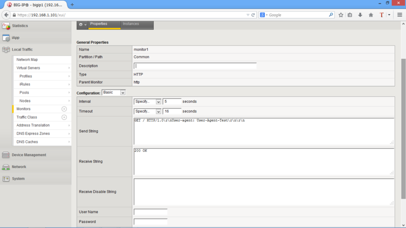
BIG-IP では HTTP のヘルスチェックに User-Agent を定義する事が可能です。
Monitor の作成
User-Agent が定義された monitor1 を作成
(tmos)# create ltm monitor http monitor1
(tmos)# modify ltm monitor http monitor1 destination *:* interval 5 recv "200 OK" send "GET / HTTP/1.0\\r\\nUser-agent: User-Agent-Test\\r\\n\\r\\n" time-until-up 0 timeout 16
Monitor の確認
(tmos)# show running-config ltm monitor
ltm monitor http monitor1 {
    defaults-from http
    destination *:*
    interval 5
    recv "200 OK"
    send "GET / HTTP/1.0\\r\\nUser-agent: User-Agent-Test\\r\\n\\r\\n"
    time-until-up 0
    timeout 16
}
GUI で設定する場合は下記のとおり
Pool の作成
Pool 作成と monitor1 の関連付け
(tmos)# create ltm pool pool1
(tmos)# modify ltm pool pool1 members add { 192.168.100.1:http { address 192.168.100.1 } } monitor monitor1
Pool の確認
(tmos)# show running-config ltm pool pool1
ltm pool pool1 {
    members {
        192.168.100.1:http {
            address 192.168.100.1
            session monitor-enabled
            state up
        }
    }
    monitor monitor1
}
サーバで User-Agent が定義された HTTP リクエストを受信している事を確認
> tcpdump -i eth1 -s 1024 -A dst 192.168.100.1 and port 80
tcpdump: verbose output suppressed, use -v or -vv for full protocol decode
listening on eth1, link-type EN10MB (Ethernet), capture size 1024 bytes
08:17:12.102234 IP 192.168.100.254.56048 > 192.168.100.1.http: S 3813966378:3813966378(0) win 14600 <mss 1460,sackOK,timestamp 4216260931 0,nop,wscale 7>
E..<.4@.@.j7..d...d....P.T.*......9..T.........
.O      C........
08:17:12.145874 IP 192.168.100.254.56048 > 192.168.100.1.http: . ack 3041341077 win 115 <nop,nop,timestamp 4216260950 2122782>
E..4.5@.@.j>..d...d....P.T.+.G.....s.w.....
.O      V. d.
08:17:12.145882 IP 192.168.100.254.56048 > 192.168.100.1.http: P 0:47(47) ack 1 win 115 <nop,nop,timestamp 4216260950 2122782>
E..c.6@.@.j...d...d....P.T.+.G.....s.......
.O      V. d.GET / HTTP/1.0
User-agent: User-Agent-Test  <--- BIG-IP で定義した文字列を確認
以上
便利なスクリプト(CentOS)
Ping を実行した際、Windows のように"Request Timed out"を表示させる。
[root@hostname ~]# host=***.***.***.***; max_cnt=10; cnt=0; while [ $cnt -le $max_cnt ]; do rslt=`ping -w 1 -c 1 $host | grep 'bytes from '`; if [ $? -gt 0 ]; then echo -e "`date +'%H:%M:%S'` $host Request timed out."; else echo "`date +'%H:%M:%S'` $host`echo $rslt | cut -d ':' -f 2`"; sleep 1; fi; cnt=$(expr $cnt + 1); done;
任意のコマンド(例:df -h)を 5秒間隔で繰り返し実行する。
[username@hostname]$ while true; do date; df -h; sleep 5; clear; done;
参考:http://sonic64.com/2004-05-28.html
以上
Junos Shaping 設定
Junos の Shaping 機能についてテストした際の備忘録です。スループット測定は iperf を使用しました。
iperf の準備
epel リポジトリインストール
# wget http://dl.fedoraproject.org/pub/epel/5/x86_64/epel-release-5-4.noarch.rpm
# wget http://rpms.famillecollet.com/enterprise/remi-release-5.rpm
# rpm -Uvh remi-release-5*.rpm epel-release-5*.rpm
iperf インストール
# yum install -y iperf
iperf 起動(サーバ側:192.168.100.1)
# iperf -s
------------------------------------------------------------
Server listening on TCP port 5001
TCP window size: 85.3 KByte (default)
------------------------------------------------------------
スループット測定
Shaping 設定前
# iperf -c 192.168.100.1
------------------------------------------------------------
Client connecting to 192.168.100.1, TCP port 5001
TCP window size: 16.0 KByte (default)
------------------------------------------------------------
[  3] local 100.64.1.1 port 38985 connected with 192.168.100.1 port 5001
[ ID] Interval       Transfer     Bandwidth
[  3]  0.0-10.0 sec   845 MBytes   708 Mbits/sec
Shaping(200Mbps)設定後
# iperf -c 192.168.100.1
------------------------------------------------------------
Client connecting to 192.168.100.1, TCP port 5001
TCP window size: 16.0 KByte (default)
------------------------------------------------------------
[  3] local 100.64.1.1 port 36607 connected with 192.168.100.1 port 5001
[ ID] Interval       Transfer     Bandwidth
[  3]  0.0-10.0 sec   221 MBytes   185 Mbits/sec
Junos Shaping 設定例
# set class-of-service interfaces ge-0/0/1 scheduler-map Smap_Shaping
# set class-of-service scheduler-maps Smap_Shaping forwarding-class best-effort scheduler Shaping
# set class-of-service scheduler-maps Smap_Shaping forwarding-class expedited-forwarding scheduler Shaping
# set class-of-service scheduler-maps Smap_Shaping forwarding-class assured-forwarding scheduler Shaping
# set class-of-service scheduler-maps Smap_Shaping forwarding-class network-control scheduler Shaping
# set class-of-service schedulers Shaping shaping-rate 300m
# set class-of-service schedulers Shaping priority low
Python で Cisco のログを取得
Python で Cisco のログを収集する際のスクリプト例です。
Exscript で上手くいかずハマってしまったため、とりあえず Paramiko を使用しました。
"ssh.exec_command" で複数のコマンドを実行できないため、少し不便です。(方法があるかもですが。。)
import paramiko
import datetime, time
import cmd
import sys

hostname  = 'myrouter'
ipaddress = '192.168.1.1'
username  = 'username'
password  = 'password'
date = datetime.date.today().strftime("%Y-%m-%d")

ssh = paramiko.SSHClient()
ssh.set_missing_host_key_policy(paramiko.AutoAddPolicy())
ssh.connect(ipaddress, username=username, password=password)
stdin, stdout, stderr = ssh.exec_command('show tech-support unprivileged')
# print stdout.read()

open_file = stdout.read()
config_file = open(hostname+"-"+date+".cfg","w")
config_file.write(open_file)
config_file.close()
ssh.close()
print "Finished python wrote "+hostname+"-"+date+".cfg"
参考書籍
リンク
以上
CentOS6.3 に Python2.7.3 をインストール
インストール手順
zlib のヘッダファイル・ライブラリのインストール
※インストールしていないとエラー*1が発生し、Distribute のインストールに失敗する場合があります。
[root@hostname ~]# yum install zlib-devel
OpenSSL development のインストール
※インストールしていないとエラー*2が発生し、pip のインストールに失敗する場合があります。
[root@hostname ~]# yum install openssl-devel
Python2.7.3 のインストール
Python2.7.3 をダウンロードして解凍
[root@hostname ~]# wget --no-check-certificate http://www.python.org/ftp/python/2.7.3/Python-2.7.3.tgz
[root@hostname ~]# tar zxvf Python-2.7.3.tgz
コンパイルとインストール
[root@hostname ~]# cd Python-2.7.3
[root@hostname ~]# ./configure --prefix=/usr/local
[root@hostname ~]# make
[root@hostname ~]# make altinstall
Distribute のインストール
Distribute をダウンロードして解凍
[root@hostname ~]# wget --no-check-certificate http://pypi.python.org/packages/source/d/distribute/distribute-0.6.27.tar.gz
[root@hostname ~]# tar zxvf distribute-0.6.27.tar.gz
Distribute をインストール
[root@hostname ~]# cd distribute-0.6.27
[root@hostname ~]# python2.7 setup.py install
pip のインストール
easy_install-2.7 で pip をインストール
[root@hostname ~]# easy_install-2.7 pip
Paramiko のインストール
pip コマンドで paramiko をインストール
[root@hostname ~]# pip install paramiko
paramiko が読み込める事を確認(SSH 関連のみ抜粋)
[root@hostname ~]# python2.7
Python 2.7.3 (default, Apr  6 2014, 00:41:52)
[GCC 4.4.6 20120305 (Red Hat 4.4.6-4)] on linux2
Type "help", "copyright", "credits" or "license" for more information.
>>> import paramiko
>>> filter(lambda s: s.startswith("SSH"), dir(paramiko))
['SSHClient', 'SSHConfig', 'SSHException']
モジュールの一覧を確認(抜粋)
[root@hostname ~]#  python -c "help('modules')"
Please wait a moment while I gather a list of all available modules...
BaseHTTPServer      calendar            imaplib             rlcompleter
Bastion             cgi                 imghdr              robotparser
CDROM               cgitb               imp                 rpm
CGIHTTPServer       chunk               imputil             rpmUtils
CORBA               cmath               iniparse            runpy
ConfigParser        cmd                 inspect             scanext
Cookie              code                invest              scdate
DLFCN               codecs              io                  sched
<...snip...>
Exscript のインストール
pip コマンドで Exscript をインストール
[root@hostname ~]# pip install https://github.com/knipknap/exscript/tarball/master
Exscript のバージョンを確認
[root@hostname ~]# exscript --version
DEVELOPMENT
以上
wget で https 通信に失敗する際の対処方法
wget で https 経由でファイルをダウンロードする際、下記のようなエラーが出力される場合があります。
[root@hostname ~]# wget https://www.python.org/ftp/python/2.7.3/Python-2.7.3.tgz
wget: Syntax error in /etc/wgetrc at line 127.
--2014-03-20 23:35:24--  https://www.python.org/ftp/python/2.7.3/Python-2.7.3.tgz
Resolving www.python.org... 103.245.222.143
Connecting to www.python.org|103.245.222.143|:443... connected.
ERROR: certificate common name “b.ssl.fastly.net” doesn’t match requested host name “www.python.org”.
To connect to www.python.org insecurely, use ‘--no-check-certificate’.
メッセージにあるとおり"--no-check-certificate" を付与する事で可能となります。
[root@hostname ~]# wget --no-check-certificate https://www.python.org/ftp/python/2.7.3/Python-2.7.3.tgz
wget: Syntax error in /etc/wgetrc at line 127.
--2014-03-20 23:33:56--  https://www.python.org/ftp/python/2.7.3/Python-2.7.3.tgz
Resolving www.python.org... 103.245.222.143
Connecting to www.python.org|103.245.222.143|:443... connected.
WARNING: certificate common name “b.ssl.fastly.net” doesn’t match requested host name “www.python.org”.
HTTP request sent, awaiting response... 301 Moved Permanently
Location: http://legacy.python.org/ftp//python/2.7.3/Python-2.7.3.tgz [following]
--2014-03-20 23:33:56--  http://legacy.python.org/ftp//python/2.7.3/Python-2.7.3.tgz
Resolving legacy.python.org... 82.94.164.162, 2001:888:2000:d::a2
Connecting to legacy.python.org|82.94.164.162|:80... connected.
HTTP request sent, awaiting response... 200 OK
以上
Cisco ASA 設定覚書
検証環境

設定例
リモートアクセス設定
SSH 接続設定
ciscoasa(config)# username admin password cisco privilege 15
ciscoasa(config)# aaa authentication ssh console LOCAL
ciscoasa(config)# ssh 0 0 management
ciscoasa(config)# ssh timeout 10
ciscoasa(config)# crypto key generate rsa general-keys modulus 1024 noconfirm
HA 設定
Primary 側インターフェース設定
ciscoasa(config)# interface gigabitEthernet 0/0
ciscoasa(config-if)# nameif outside
ciscoasa(config-if)# ip address 192.168.10.251 255.255.255.0 standby 192.168.10.252
ciscoasa(config-if)# int gigabitEthernet 0/0
ciscoasa(config-if)# nameif inside
ciscoasa(config-if)# ip address 192.168.20.251 255.255.255.0 standby 192.168.20.252
ciscoasa(config-if)# exit
Primary 側 Failover 設定
ciscoasa(config)# failover lan unit primary
ciscoasa(config)# failover lan interface failover GigabitEthernet0/2
ciscoasa(config)# failover interface ip failover 10.1.1.1 255.255.255.0 standby 10.1.1.2
ciscoasa(config)# failover link state GigabitEthernet0/3
ciscoasa(config)# failover interface ip state 10.1.2.1 255.255.255.0 standby 10.1.2.2
Secondary 側 Failover 設定
ciscoasa(config)# failover lan interface failover GigabitEthernet0/2
ciscoasa(config)# failover interface ip failover 10.1.1.1 255.255.255.0 standby 10.1.1.2
Primary 側インターフェース有効化
ciscoasa(config-if)# interface gigabitEthernet 0/0
ciscoasa(config-if)# no shutdown
ciscoasa(config-if)# interface gigabitEthernet 0/1
ciscoasa(config-if)# no shutdown
ciscoasa(config-if)# interface gigabitEthernet 0/2
ciscoasa(config-if)# no shutdown
ciscoasa(config-if)# interface gigabitEthernet 0/3
ciscoasa(config-if)# no shutdown
Secondary 側インターフェース有効化
ciscoasa(config-if)# interface gigabitEthernet 0/0
ciscoasa(config-if)# no shutdown
ciscoasa(config-if)# interface gigabitEthernet 0/1
ciscoasa(config-if)# no shutdown
ciscoasa(config-if)# interface gigabitEthernet 0/2
ciscoasa(config-if)# no shutdown
ciscoasa(config-if)# interface gigabitEthernet 0/3
ciscoasa(config-if)# no shutdown
Primary 側 Failover 有効化
ciscoasa(config)# failover
Secondary 側 Failover 有効化
ciscoasa(config)# failover
Failover 状態確認
ciscoasa# show failover state

               State          Last Failure Reason      Date/Time
This host  -   Primary
               Active         None
Other host -   Secondary
               Standby Ready  None

====Configuration State===
        Sync Done - STANDBY
====Communication State===
        Mac set
ファイアウォール設定
アクセスリストの設定(outside から inside への icmp/http/https 許可)
ciscoasa(config)# object-group service DM_INLINE_SERVICE_1
ciscoasa(config-service-object-group)# service-object icmp
ciscoasa(config-service-object-group)# service-object tcp destination eq www
ciscoasa(config-service-object-group)# service-object tcp destination eq https
ciscoasa(config)# access-list outside_access_in extended permit object-group DM_INLINE_SERVICE_1 192.168.10.0 255.255.255.0 192.168.20.0 255.255.255.0
ciscoasa(config)# access-group outside_access_in in interface outside
ポートスキャン試験(Client→Web Server)
Nmap によるポートスキャン
[root@hostname ~]# nmap -v -sS 192.168.20.101

Starting Nmap 4.11 ( http://www.insecure.org/nmap/ ) at 2014-02-21 08:41 PST
DNS resolution of 1 IPs took 0.01s.
Initiating SYN Stealth Scan against 192.168.20.101 [1680 ports] at 08:41
Discovered open port 80/tcp on 192.168.20.101
The SYN Stealth Scan took 25.15s to scan 1680 total ports.
Host 192.168.20.101 appears to be up ... good.
Interesting ports on 192.168.20.101:
Not shown: 1678 filtered ports
PORT    STATE  SERVICE
80/tcp  open   http
443/tcp closed https

Nmap finished: 1 IP address (1 host up) scanned in 25.336 seconds
               Raw packets sent: 3364 (147.996KB) | Rcvd: 7 (322B)
Remote Access VPN 設定
ASA 設定
ciscoasa(config)# ip local pool pool 172.16.1.1-172.16.1.10 mask 255.255.255.0
ciscoasa(config)# webvpn
ciscoasa(config-webvpn)# enable outside
ciscoasa(config-webvpn)# anyconnect image disk0:/anyconnect-linux-64-3.1.0515$
ciscoasa(config-webvpn)# anyconnect enable
ciscoasa(config-webvpn)# tunnel-group-list enable
ciscoasa(config-webvpn)# group-policy DfltGrpPolicy attributes
ciscoasa(config-group-policy)# vpn-tunnel-protocol ikev1 l2tp-ipsec ssl-clien$
ciscoasa(config-group-policy)# group-policy GroupPolicy_WebVPN internal
ciscoasa(config)# group-policy GroupPolicy_WebVPN attributes
ciscoasa(config-group-policy)# wins-server none
ciscoasa(config-group-policy)# dns-server value 8.8.8.8
ciscoasa(config-group-policy)# vpn-tunnel-protocol ssl-client
ciscoasa(config-group-policy)# default-domain none
ciscoasa(config-group-policy)# tunnel-group WebVPN type remote-access
ciscoasa(config)# tunnel-group WebVPN general-attributes
ciscoasa(config-tunnel-general)# address-pool pool
ciscoasa(config-tunnel-general)# default-group-policy GroupPolicy_WebVPN
ciscoasa(config-tunnel-general)# tunnel-group WebVPN webvpn-attributes
ciscoasa(config-tunnel-webvpn)# group-alias WebVPN enable
Client から HTTPS 接続

Link から AnyConnect Secure Mobility Client をダウンロード
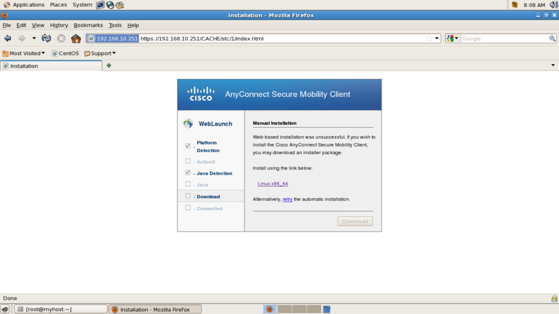
vpnsetup.sh. ファイルをオープン

Could not open the file /tmp/vpnsetup.sh. エラー

vpnsetup.sh 実行
[root@hostname ~]# chmod 755 vpnsetup.sh
[root@hostname ~]# ./vpnsetup.sh
Installing Cisco AnyConnect Secure Mobility Client...
Extracting installation files to /tmp/vpn.G11283/vpninst502577000.tgz...
Unarchiving installation files to /tmp/vpn.G11283...
Starting Cisco AnyConnect Secure Mobility Client Agent...
Done!
Cisco AnyConnect Secure Mobility Client 起動

アドレスを設定し[Connect]

Group、Username、Passoword を設定し[Connect]

WebVPN 接続確認(ASA)
ciscoasa# show vpn-sessiondb anyconnect

Session Type: AnyConnect

Username     : admin                  Index        : 177
Assigned IP  : 172.16.1.1             Public IP    : 192.168.10.101
Protocol     : AnyConnect-Parent SSL-Tunnel DTLS-Tunnel
License      : AnyConnect Premium
Encryption   : AnyConnect-Parent: (1)none  SSL-Tunnel: (1)RC4  DTLS-Tunnel: (1)AES128
Hashing      : AnyConnect-Parent: (1)none  SSL-Tunnel: (1)SHA1  DTLS-Tunnel: (1)SHA1
Bytes Tx     : 8258                   Bytes Rx     : 782
Group Policy : GroupPolicy_WebVPN     Tunnel Group : WebVPN
Login Time   : 04:11:17 UTC Fri Feb 21 2014
Duration     : 0h:00m:05s
Inactivity   : 0h:00m:00s
VLAN Mapping : N/A                    VLAN         : none
Audt Sess ID : c0a814fb000b10005306d1e5
Security Grp : 0
WebVPN 接続確認(Client)
[root@hostname ~]# ifconfig cscotun0
cscotun0  Link encap:UNSPEC  HWaddr 00-00-00-00-00-00-00-00-00-00-00-00-00-00-00-00
          inet addr:172.16.1.1  P-t-P:172.16.1.1  Mask:255.255.255.0
          UP POINTOPOINT RUNNING NOARP MULTICAST  MTU:1406  Metric:1
          RX packets:0 errors:0 dropped:0 overruns:0 frame:0
          TX packets:0 errors:0 dropped:0 overruns:0 carrier:0
          collisions:0 txqueuelen:500
          RX bytes:0 (0.0 b)  TX bytes:0 (0.0 b)
以上
Telnet を使用した HTTP/MAIL 確認方法
Telnet を使用して、HTTP や MAIL のテストをすることができます。
HTTP 確認方法
Telnet を使用して、Web サイトへアクセスします。
# telnet localhost 80
Trying 127.0.0.1...
Connected to localhost.localcomain (127.0.0.1).
Escape character is '^]'.
GET http://localhost/index.html HTTP/1.0

HTTP/1.1 200 OK
Date: Fri, 21 Feb 2014 02:43:08 GMT
Server: Apache/2.2.3 (CentOS)
Last-Modified: Fri, 21 Feb 2014 02:28:46 GMT
ETag: "30313-5-4f2e1619bb380"
Accept-Ranges: bytes
Content-Length: 5
Connection: close
Content-Type: text/html; charset=UTF-8

test
Connection closed by foreign host.
プロキシの試験も可能です。
# telnet localhost 3128
Trying 127.0.0.1...
Connected to localhost.localcomain (127.0.0.1).
Escape character is '^]'.
GET http://192.168.1.152/index.html HTTP/1.0

HTTP/1.0 200 OK
Date: Fri, 21 Feb 2014 11:28:36 GMT
Server: Apache/2.2.3 (CentOS)
Last-Modified: Fri, 21 Feb 2014 02:34:11 GMT
ETag: "1502d2-5-4f2e174facec0"
Accept-Ranges: bytes
Content-Length: 5
Content-Type: text/html; charset=UTF-8
Age: 1344
X-Cache: HIT from myhost
X-Cache-Lookup: HIT from myhost:3128
Via: 1.0 myhost:3128 (squid/2.6.STABLE21)
Proxy-Connection: close

test
Connection closed by foreign host.
アクセスログから、プロキシ経由となっている事を確認します。
# tail -f /var/log/squid/access.log
1392982116.127    918 127.0.0.1 TCP_MISS/200 385 GET http://192.168.1.152/index.html - DIRECT/192.168.1.152 text/html
1392982262.706    179 127.0.0.1 TCP_HIT/200 393 GET http://192.168.1.152/index.html - NONE/- text/html
MAIL 確認方法
Telnet を使用して、メールを送信します。
# telnet localhost smtp
Trying 127.0.0.1...
Connected to localhost.localdomain (127.0.0.1).
Escape character is '^]'.
220 host01.example.com ESMTP
HELO TEST
250 host01.example.com
MAIL FROM:user01@example.com
250 2.1.0 Ok
RCPT TO:user02@exmaple.com
250 2.1.5 Ok
DATA
354 End data with <CR><LF>.<CR><LF>
subject:testmail
this is testmail.
.
250 2.0.0 Ok: queued as DD8DC4400B2
QUIT
221 2.0.0 Bye
Connection closed by foreign host.
以上
HA コントローラ構成における NVRAM について
NetApp の HA 概要
NetApp のコントローラを HA で構成した場合、各コントローラ上の NVRAM の半分がパートナーデータのミラー用として、リザーブされます。(使用できる NVRAM が 非 HA 構成と比較し 1/2 になります。)
Takeover 発生時、残ったコントローラは、このミラー用の NVRAM を使用して、ダウンコントローラの Read/Write を処理します。つまり、Takeover が発生した際には、NVRAM は縮退せず、CPU /Memory のみ縮退するという事になります。
NVRAM During Normal Mode

以上
vSphere PowerCLI 覚書
セキュリティポリシーの変更(スクリプトの実行を許可)
PS C:\> Set-ExecutionPolicy RemoteSigned
vCenter サーバーへ接続
PS C:\> Connect-VIServer -User Administrator@vsphere.local -Password P@ssw0rd 192.168.1.10
新規データセンタの作成
PS C:\> $folder = Get-Folder -NoRecursion | New-Folder -Name Folder
PS C:\> New-Datacenter -Location $folder -Name Datacenter | fl
データセンターににホスト(192.168.1.11)を追加
PS C:\> $myServer = Connect-VIServer -Server 192.168.1.10
PS C:\> Add-VMHost -Server $myServer -Name 192.168.1.11 -Location Datacenter -User root -Password password -Force
Name                 ConnectionState PowerState NumCpu CpuUsageMhz CpuTotalMhz   MemoryUsageGB   MemoryTotalGB Version
----                 --------------- ---------- ------ ----------- -----------   -------------   ------------- -------
192.168.1.11         Connected       PoweredOn       2         169        6784           1.080           4.000   5.5.0
データセンターに登録済のホストを確認
PowerCLI C:\> Get-VMHost
Name                 ConnectionState PowerState NumCpu CpuUsageMhz CpuTotalMhz   MemoryUsageGB   MemoryTotalGB Version
----                 --------------- ---------- ------ ----------- -----------   -------------   ------------- -------
192.168.1.11         Connected       PoweredOn       2          71        6784           1.081           4.000   5.5.0
192.168.1.12         Connected       PoweredOn       2          63        6784           1.081           4.000   5.5.0
192.168.1.* のホストに vSwitch1 を作成
Get-VMhost 192.168.1.* | New-VirtualSwitch -Name vSwitch1 -Nic vmnic1
vSwitch 情報の確認
PowerCLI C:\> Get-VirtualSwitch -VMHost 192.168.1.11 | fl
Id                : key-vim.host.VirtualSwitch-vSwitch0
Key               : key-vim.host.VirtualSwitch-vSwitch0
Name              : vSwitch0
NumPorts          : 1536
NumPortsAvailable : 1531
Nic               : {vmnic0}
Mtu               : 1500
VMHostId          : HostSystem-host-30
VMHost            : 192.168.1.11
VMHostUid         : /VIServer=administrator@vsphere.local@192.168.1.10:443/VMHost=HostSystem-host-30/
Uid               : /VIServer=administrator@vsphere.local@192.168.1.10:443/VMHost=HostSystem-host-30/VirtualSwitch=key-vim.host.VirtualSwitch-vSwitch0/
ExtensionData     : VMware.Vim.HostVirtualSwitch
vSwitch ポートグループ情報の確認
PowerCLI C:\> Get-VirtualPortGroup -VMHost 192.168.1.11 | ft -autosize
Name               Key                                       VLanId PortBinding NumPorts
----               ---                                       ------ ----------- --------
VM Network         key-vim.host.PortGroup-VM Network         0
Management Network key-vim.host.PortGroup-Management Network 0
vSwitch1 に vMotion 用の vmkernel ポートを作成
PowerCLI C:\> $vmhost = Get-VMHost -Name 192.168.1.11
PowerCLI C:\> $myVirtualSwitch = Get-VirtualSwitch -VMHost $vmhost -Name vSwitch1
PowerCLI C:\> New-VMHostNetworkAdapter -VMHost $vmhost -PortGroup vMotion -VirtualSwitch $myVirtualSwitch -IP 172.16.1.11 -SubnetMask 255.255.255.0 -VMotionEnabled 1
vmkernel ポートの情報確認
PowerCLI C:\> Get-VMHostNetworkAdapter -VMHost 192.168.1.11 | Where-Object{$_.Name -eq "vmk1"} | fl
VMotionEnabled               : True
FaultToleranceLoggingEnabled : False
ManagementTrafficEnabled     : False
IPv6                         : {fe80::250:56ff:fe6d:b200/64}
AutomaticIPv6                : False
IPv6ThroughDhcp              : False
IPv6Enabled                  : False
Mtu                          : 1500
VsanTrafficEnabled           : False
PortGroupName                : vMotion
Id                           : key-vim.host.VirtualNic-vmk1
VMHostId                     : HostSystem-host-30
VMHost                       : 192.168.1.11
VMHostUid                    : /VIServer=administrator@vsphere.local@192.168.1.10:443/VMHost=HostSystem-host-30/
DeviceName                   : vmk1
Mac                          : 00:50:56:6d:b2:00
DhcpEnabled                  : False
IP                           : 172.16.1.11
SubnetMask                   : 255.255.255.0
Uid                          : /VIServer=administrator@vsphere.local@192.168.1.10:443/VMHost=HostSystem-host-30/HostVMKernelVirtualNic=key-vim.host.VirtualNic-vmk1/
Name                         : vmk1
ExtensionData                : VMware.Vim.HostVirtualNic
ホストのネットワークアダプタ状態の確認
PowerCLI C:\> Get-VMHostNetworkAdapter -VMHost 192.168.1.* | ft -autosize
Name   Mac               DhcpEnabled IP           SubnetMask    DeviceName
----   ---               ----------- --           ----------    ----------
vmnic0 00:0c:29:b7:42:58 False                                      vmnic0
vmnic1 00:0c:29:b7:42:62 False                                      vmnic1
vmnic2 00:0c:29:b7:42:6c False                                      vmnic2
vmnic3 00:0c:29:b7:42:76 False                                      vmnic3
vmk0   00:0c:29:b7:42:58 False       192.168.1.11 255.255.255.0       vmk0
vmk1   00:50:56:6d:b2:00 False       172.16.1.11  255.255.255.0       vmk1
vmnic0 00:0c:29:04:5e:52 False                                      vmnic0
vmnic1 00:0c:29:04:5e:5c False                                      vmnic1
vmnic2 00:0c:29:04:5e:66 False                                      vmnic2
vmnic3 00:0c:29:04:5e:70 False                                      vmnic3
vmk0   00:0c:29:04:5e:52 False       192.168.1.12 255.255.255.0       vmk0
vmk1   00:50:56:68:0f:b6 False       172.16.1.12  255.255.255.0       vmk1
分散スイッチの作成
PowerCLI C:\> $myDatacenter = Get-Datacenter -Name Datacenter
PowerCLI C:\> New-VDSwitch -Name "VDSwitch" -Location $myDatacenter -NumUplinkPorts 1
分散スイッチへホストを追加
PowerCLI C:\> Get-VDSwitch -Name "VDSwitch" | Add-VDSwitchVMHost -VMHost "192.168.1.11", "192.168.1.12"
分散スイッチのアップリンクポートへ物理アダプタを追加
PowerCLI C:\> $vmhostNetworkAdapter = Get-VMHost "192.168.1.*" | Get-VMHostNetworkAdapter -Physical -Name vmnic2
PowerCLI C:\> Get-VDSwitch "VDSwitch" | Add-VDSwitchPhysicalNetworkAdapter -VMHostNetworkAdapter $vmhostNetworkAdapter
分散スイッチへポートグループを追加
Get-VDSwitch -Name "VDSwitch" | New-VDPortgroup -Name "VDPortGroup"
分散スイッチ情報の確認
PowerCLI C:\> Get-VDSwitch -VMHost 192.168.1.*
Name                           NumPorts   Mtu        Version  Vendor
----                           --------   ---        -------  ------
VDSwitch                       8          1500       5.5.0    VMware
分散スイッチポートグループ名の変更
Get-VDPortgroup -Name "VDPortGroup" | Set-VDPortgroup -Name "VDPortGroup2"
仮想マシンの作成。Guest ID の詳細は こちら
PowerCLI C:\> $myTargetVMHost = Get-VMHost -Name 192.168.1.11
PowerCLI C:\> New-VM -Name MyVM1 -ResourcePool $myTargetVMHost -Datastore Datastore1 -NumCPU 1 -MemoryGB 1 -DiskGB 40 -NetworkName "VM Network" -CD -DiskStorageFormat Thin -GuestID centosGuest
仮想マシンを OVF から作成
PowerCLI C:\> $myDatastore = Get-Datastore -Name "Datastore1"
PowerCLI C:\> $vmHost = Get-VMHost -Name "192.168.1.11"
PowerCLI C:\> $vmHost | Import-vApp -Name dc1-otv -Source "c:\csr1000v-universalk9.03.11.00.S.154-1.S-std-C1-M2560-N3-DS8.ova" -Datastore $myDatastore -Force
仮想マシンに適用しているポートグループの変更
get-vm -name MyVM1 | Get-NetworkAdapter | Where-Object{$_.NetworkName -eq "VM Network"} | Set-NetworkAdapter -Portgroup VDPortGroup
x-vMotion の実行
PowerCLI C:\> Move-VM -VM MyVM1 -Destination 192.168.1.12 -Datastore datastore2
vCenter サーバーを切断
PowerCLI C:\> Disconnect-VIServer -Server 192.168.1.10 -Confirm:$False