vSwitch でミラーリングを設定する
標準スイッチでは、分散スイッチと異なり、ポートをミラーリング機能をサポートしていませんが、任意の仮想マシンにパケットをミラーする事が可能です。
標準スイッチの作成
「Networking」タブで「Virtual switches」を選択し「Add host Networking」をクリックします。

「Virtual Machine Port Group for a Standard Switch」を選択し「Next」をクリックします。

「New Standard Switch」を選択し「Next」をクリックします。

試験のため NIC はアサインせず、「Next」をクリックします。

VLAN ID を「ALL(4095)」に指定し「Next」をクリックします。

内容を確認し「Finish」をクリックします。

標準スイッチが作成されている事を確認します。

仮想マシンへのポートグループ設定
現在、仮想マシンは分散スイッチのポートグループをアサインしているので、作成したスイッチへ移行します。
「Networking」タブで「DSwitch」を右クリックし「Migrate VM to Another Network」をクリックします。

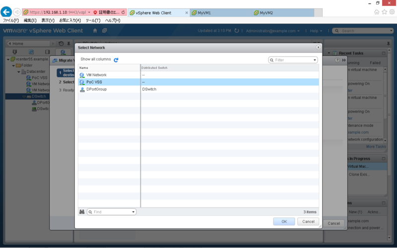
Source Network の「Specific Network」で「Browse」をクリックします。

移行元(分散スイッチ)のポートグループを選択して「OK」をクリックします。

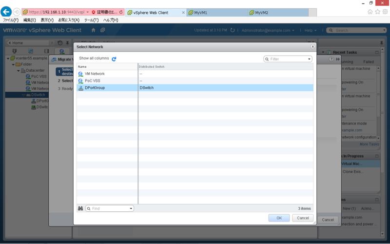
Destination Network の「Specific Network」で「Browse」をクリックします。

移行先(標準スイッチ)のポートグループを選択して「OK」をクリックします。

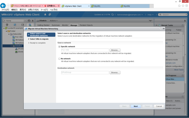
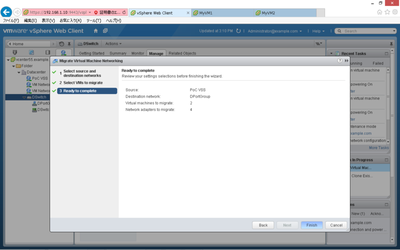
内容を確認し「Next」をクリックします。

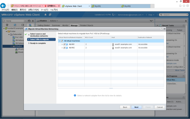
移行対象の仮想マシンを選択して「Next」をクリックします。

内容を確認し「Finish」をクリックします。

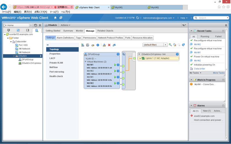
対象の仮想マシンが標準スイッチに移行している事を確認します。

ミラーリングの設定
テストのため、MyVM1 から MyVM3へ Ping し、MyVM2 で tcpdump を実行します。
現時点では、MyVM2 にパケットが転送されていません。

作成した仮想スイッチを選択し「Edit Settings」をクリックします。

「Security」の Promiscuous mode を「Accept」に変更し「OK」をクリックします。

MyVM2 にパケットが転送され、確認できるようになります。

Ontap シミュレーターで Flash Pool を試す
Flash Pool とは
HDD と SSD が混在したアグリゲートを構成し、使用頻度の高いデータを SSD のキャッシュへ集めることで、HDD へのアクセスを低減する機能になります。データを移動させるわけではなく、アクセス頻度の高いデータを ONTAP が自動で判別し、キャッシュされる事から、運用稼動は発生しません。
下記は、ユーザ数の増加に伴うスループットの傾向です。
出典:Tech OnTap
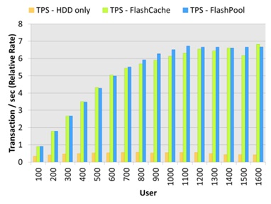
HDD のみで構成した場合、100ユーザの時点で HDD がボトルネックになり、スループットが頭打ちになっています。これに対して、Flash Pool を使用した場合は、ユーザの増加に伴い、スループットが向上しています。
Flash Pool の設定方法
ONTAP シミュレータで SSD Disk を擬似的に作成し、Flash Pool をを設定する際の手順になります。
SSD Disk の作成
Unlock the Diag user(7-Mode)
> priv set diag
*> useradmin diaguser unlock
*> useradmin diaguser password
Unlock the Diag user(Clustered Mode)
> set diag
*> security login unlock -username diag -vserver cluster1
*> security login password -username diag -vserver cluster1
Enter system shell(7-Mode)
*> systemshell
login: diag
Password:
%
Enter system shell(Clustered Mode)
*> systemshell -node cluster1-01
login: diag
Password:
%
Create SSD Disks(7-Mode/Clustered Mode)
% setenv PATH /sim/bin:$PATH
% cd /sim/dev
% sudo vsim_makedisks -t 35 -a 2 -n 14
% exit
Vefify the Disks(7-Mode)
*> disk show -n
*> sysconfig -r
Vefify the Disks(Clustered Mode)
*> disk show -container-type unassigned
*> system node run -node cluster1-01 sysconfig -r
Assign the Disks(7-Mode)
> disk assign v6.16
Assign the Disks(Clustered Mode)
> disk assign -disk v6.16 -owner cluster1-01
Flash Pool の有効化
Enable the Flash Pool(7-Mode)
> aggr options aggr1 hybrid_enabled on
> aggr add aggr1 -T SSD 14
Enable the Flash Pool(Clustered Mode)
> storage aggregate modify -aggregate aggr1 -hybrid-enabled true
> aggregate add-disks -aggregate aggr1 -disktype SSD -diskcount 14
Use the Flash Pool(7-Mode)
> vol create myvol aggr1 1g
Use the Flash Pool(Clustered Mode)
> volume create -vserver svm-01 -aggregate aggr1 -volume myvol -size 1g
以上
分散スイッチで Netflow を有効化する
Netflow は Cisco 社が開発した、ネットワークのトラフィックを収集・分析するための技術です。VMware 社の分散スイッチでは、NetFlow をサポートしており、ポートグループに流れるトラフィックを、コレクターに出力する事が可能です。
分散スイッチの設定
対象の分散スイッチを右クリックし「Manage Distributed Port Groups」をクリックします。

「Monitoring」を選択し「Next」をクリックします。

対象のポートグループを選択し「Next」をクリックします。

Netflow を「Enabled」に設定し「Next」をクリックします。

内容を確認し「Finish」をクリックします。

分散スイッチを選択し「Manage」タブの NetFlow で、コレクターの設定等を行います。

Netflow コレクタ(PRTG)の設定
「Sensors」タブから「Add Sensor」をクリックします。

「Create a new Device」を選択し「Continue」をクリックします。

Group を選択し「Continue」をクリックします。

「Device Name」「IP Address」を設定し「Continue」をクリックします。

「UDP port」「Active Flow Timeout」を設定し「Continue」をクリックします。

ポートグループ間のトラフィック状況をモニターする事が可能となります。

VMware PowerCLI サンプルスクリプト
CSV ファイルを読み込んで、仮想マシンを制御するスクリプトの例です。
本例では、仮想マシン名を記述した CSV ファイル(vms.csv)を以下のパスに配置しています。
C:\scripts\vms.csv
CSV ファイルの内容は、以下のとおりです。

仮想マシンを起動するスクリプト
$vCenterIP = "192.168.1.10"
$User = "Administrator"
$Password = "Password"
$VMs = Import-CSV C:\scripts\vms.csv

#Import the PowerCLI module
Add-PSSnapin VMware.VimAutomation.Core

#Connect to the server
$vi = Connect-VIServer -Server $vCenterIP -User $User -Password $Password

#Power on the VMs
foreach ($vm in $VMs){
      Get-VM $vm.VMName | where{$_.PowerState -eq "PoweredOff"} | Start-VM -Runasync -Confirm:$false | Out-Null
}

#Disconnect to the server
Disconnect-VIServer -Server $vCenterIP -Confirm:$False
仮想マシンを停止するスクリプト
$vCenterIP = "192.168.1.10"
$User = "Administrator"
$Password = "Password"
$VMs = Import-CSV C:\scripts\vms.csv

#Import the PowerCLI module
Add-PSSnapin VMware.VimAutomation.Core

#Connect to the server
$vi = Connect-VIServer -Server $vCenterIP -User $User -Password $Password

#Power off the VMs
foreach ($vm in $VMs){
      Get-VM $vm.VMName | where{$_.PowerState -eq "PoweredOn"} | Shutdown-VMguest -Confirm:$false | Out-Null
}

#Disconnect to the server
Disconnect-VIServer -Server $vCenterIP -Confirm:$False
仮想マシンのスナップショットを取得するスクリプト
$vCenterIP = "192.168.1.10"
$User = "Administrator"
$Password = "Password"
$Date = Get-Date -format yyyyMMddHHmm
$VMs = Import-CSV C:\scripts\vms.csv

#Import the PowerCLI module
Add-PSSnapin VMware.VimAutomation.Core

#Connect to the server
$vi = Connect-VIServer -Server $vCenterIP -User $User -

#Create the Snapshot
foreach ($vm in $VMs){
	  New-Snapshot -Name $Date -VM $vm.VMName -Descript
}

#Disconnect to the server
Disconnect-VIServer -Server $vCenterIP -Confirm:$False
仮想マシンのスナップショットを削除するスクリプト
$vCenterIP = "192.168.1.10"
$User = "Administrator"
$Password = "Password"
$Date = Get-Date -format yyyyMMddHHmm
$VMs = Import-CSV C:\scripts\vms.csv

#Import the PowerCLI module
Add-PSSnapin VMware.VimAutomation.Core

#Connect to the server
$vi = Connect-VIServer -Server $vCenterIP -User $User -Password $Password

#Remove the Snapshot
foreach ($vm in $VMs){
      Get-Snapshot -VM $vm.VMName | Remove-Snapshot -RemoveChildren -Confirm:$False
}

#Disconnect to the server
Disconnect-VIServer -Server $vCenterIP -Confirm:$False
参考書籍
リンク
以上
VMware Workstation で vFRC を試す
vFRC とは
仮想ディスクの Read Cache として、ローカルサーバの SSD を利用する仕組みを提供します。この機能により、仮想ディスクの読み込み速度が向上し、ストレージの負荷を軽減することが可能です。
詳細については、こちらをご参照ください。
事前準備
VMware Workstation では、SSD デバイスをシミュレートすることが可能です。対応する仮想マシンの vmx ファイルを編集し、SSD をシミュレートしたい SCSI デバイスを対象に下記を追記します。
scsiX:Y.virtualSSD = 1
対象の SCSI デバイスが SSD として、認識されます。
ESXi 側の vFRC の設定
Manage > Settings > Virtual Flash Resource Management > Add Capacity をクリックします。

有効な SSD デバイスが表示されるので、選択し「OK」をクリックします。

Device Backing のリストに SSD デバイスが追加されます。

ESXi ホストの vmkernel swap 領域として使用する場合は、下記の手順で行います。
Manage > Settings > Virtual Flash Host Swap Cache Configuration > Edit をクリックします。

キャッシュ容量を指定し「OK」をクリックします。

ホストキャッシュが設定されていることを確認します。

仮想マシン側の vFRC の設定
対象の仮想マシンの編集から、仮想ディスクを展開し vFRC の「Advanced」をクリックします。

キャッシュ容量とブロックサイズを指定し「OK」をクリックします。

「OK」をクリックします。

なお、この手順は、仮想マシンがパワーオン状態でも実施可能です。
vSphere Replication について
任意の仮想マシンについて、ハイパーバイザレベルでレプリケーションを実施する機能になります。
仮想マシンのコピーをハイパーバイザレベルで実施するため、データストアに依存しない点が特徴になります。

初期設定
vSphere Replication をインストール後、必要に応じて基本設定を行います。
仮想アプライアンスへの下記のアドレス・ポートでアクセス可能です。
https://IP_of_your_VR_appliance:5480

仮想アプライアンスを起動後、vCenter に VR のアイコンが追加されます。

Replication の構成例
対象の仮想マシンを選択し、右クリックから「Configure Replication」をクリックします。

vSphere Replication Server を選択し「Next」をクリックします。

Replication 先のデータストアを選択し「Next」をクリックします。

HDD をコピーする場合は「Enable disk replication」を選択し「Next」をクリックします。

「Next」をクリックします。

RPO(Recovery Point Objective)を設定し「Next」をクリックします。*3

内容を確認し「Finish」をクリックします。

Monitor > vSphere Replication > Outgoing Replication から、状態を確認できます。

仮想マシンのリカバリ
対象の仮想マシンを選択し、右クリックから「Recover」をクリックします。

Recovery options を選択し「Next」をクリックします。

仮想マシンの配置先 Folder を選択し「Next」をクリックします。

仮想マシンの配置先 Cluster を選択し「Next」をクリックします。

内容を確認し「Finish」をクリックします。

分散スイッチの作成とマイグレート
vSphere Web Client を使用した分散スイッチの作成と、標準スイッチからの移行を試してみました。
分散スイッチの作成
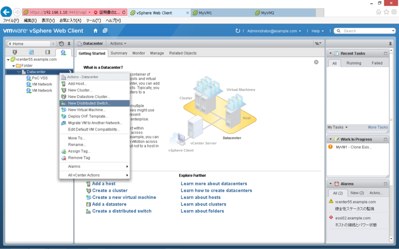
「Networking」タブで「Datacenter」を右クリックし「New Distributed Switch」をクリックします。
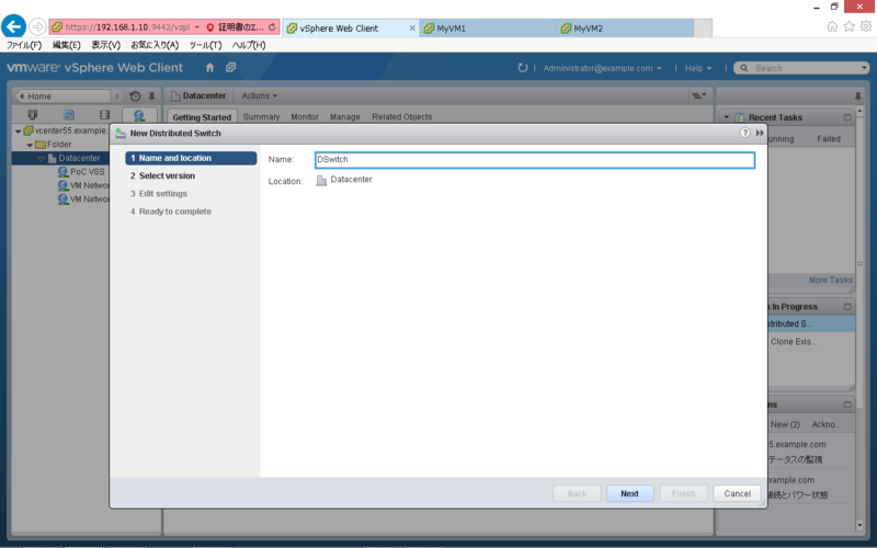
「Name」を設定し「Next」をクリックします。
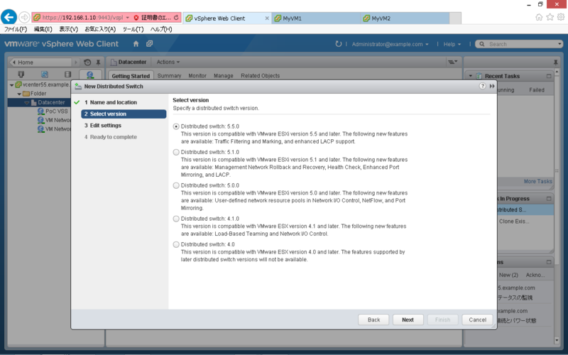
「Version」を指定し「Next」をクリックします。
「Port group name」等を設定し「Next」をクリックします。
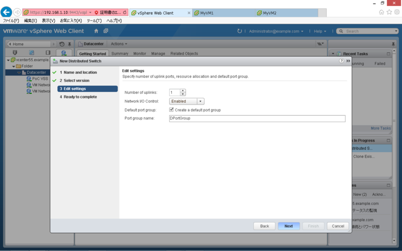
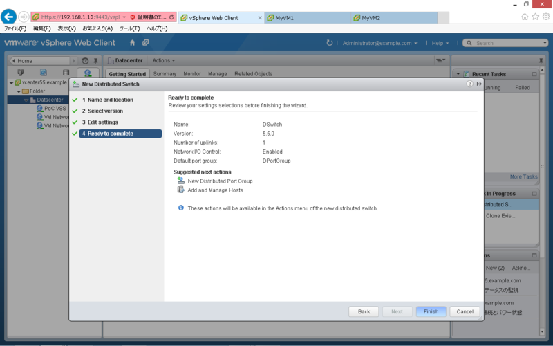
内容を確認し「Finish」をクリックします。
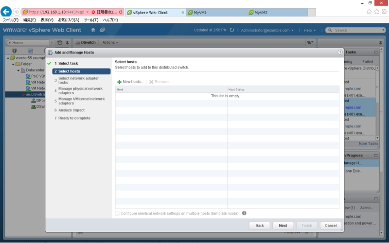
分散スイッチへのホスト登録
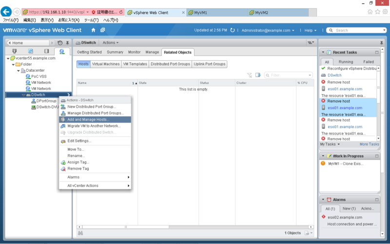
「Networking」タブで「DSwitch」を右クリックし「Add and Manage Hosts」をクリックします。
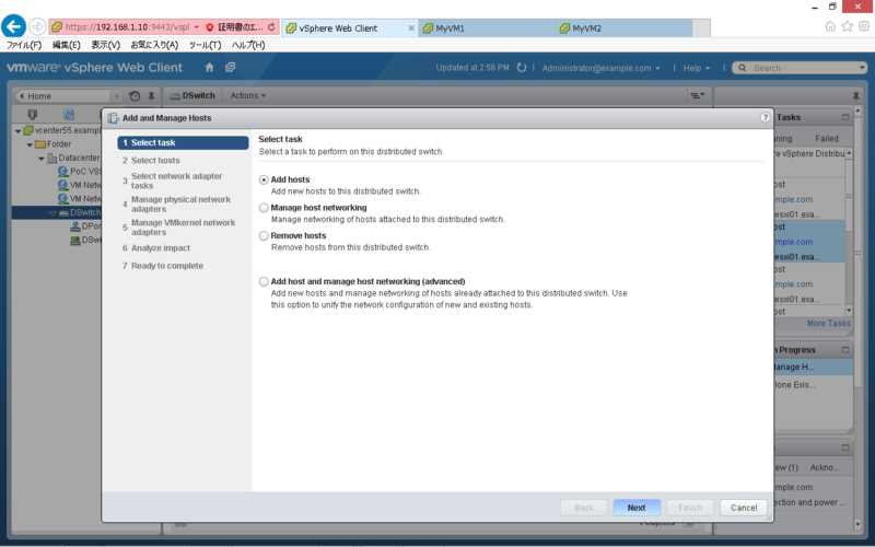
「Add hosts」を指定し「Next」をクリックします。
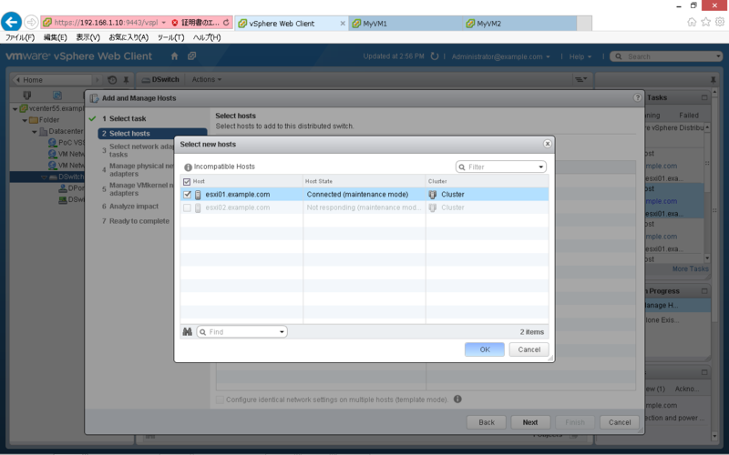
「New hosts」をクリックします。
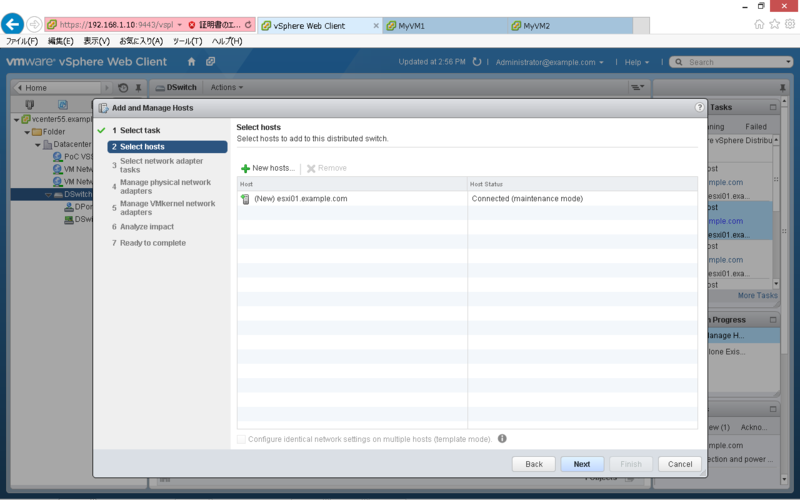
「Host」を選択し「OK」をクリックします。
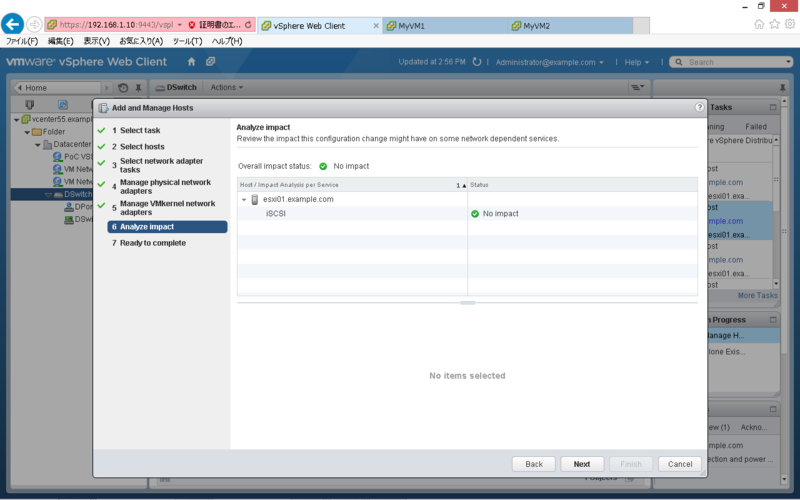
内容を確認し「Next」をクリックします。
「Next」をクリックします。
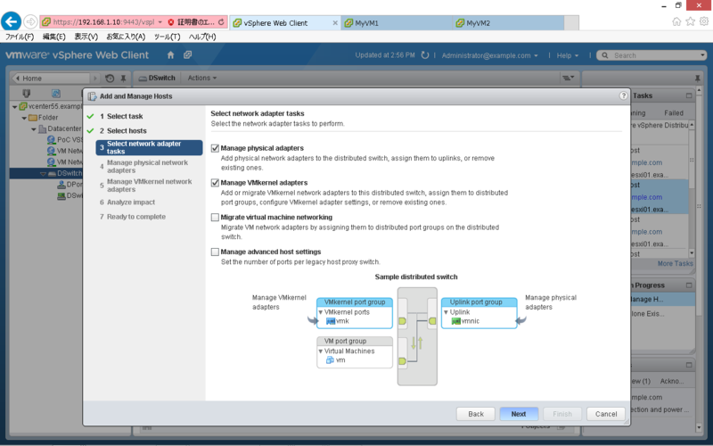
分散スイッチに追加する仮想 NIC を選択し「Assign uplink」をクリックします。
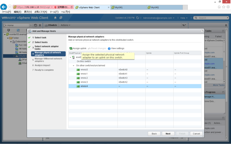
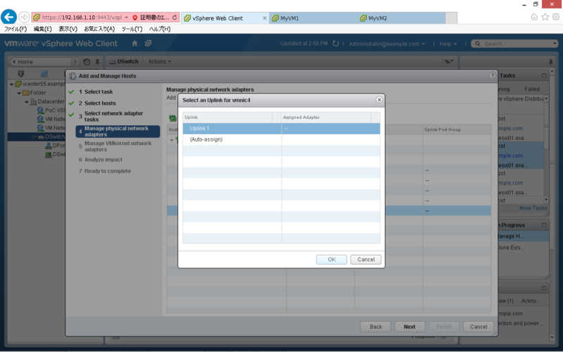
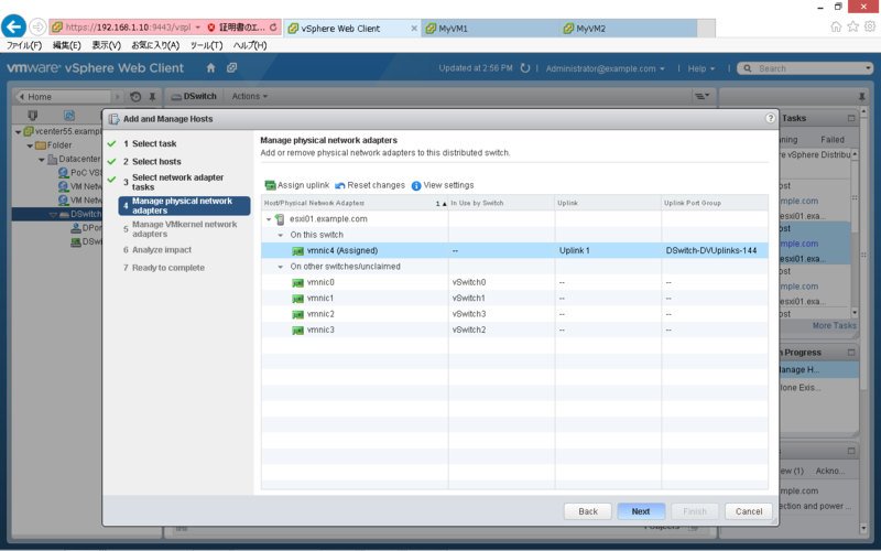
仮想 NIC を紐づける Uplink を選択し「OK」をクリックします。
内容を確認し「Next」をクリックします。
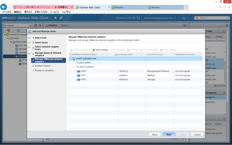
既存の vmkernel は移行対象外なので「Next」をクリックします。
「Next」をクリックします。
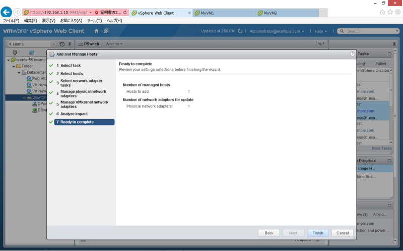
内容を確認し「Finish」をクリックします。
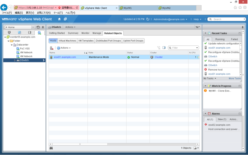
分散スイッチにホストが追加されている事を確認します。
標準スイッチから分散スイッチへの移行
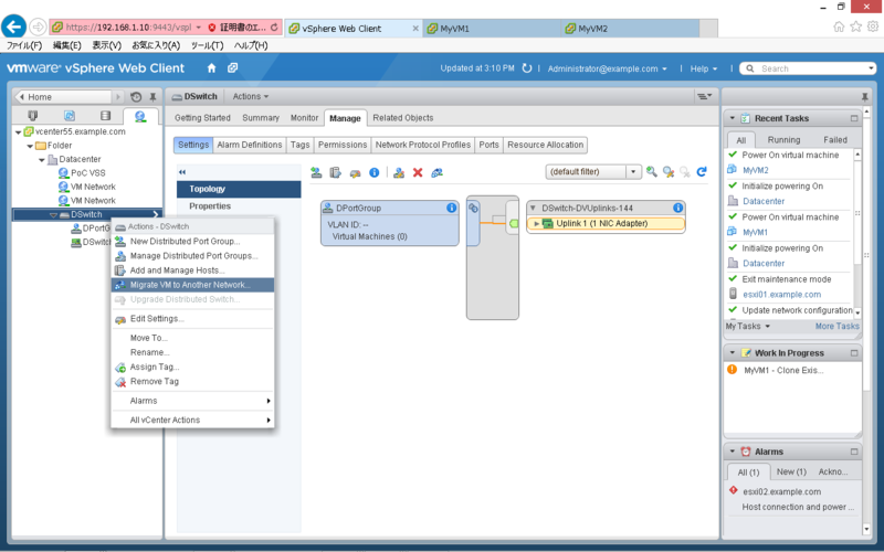
「Networking」タブで「DSwitch」を右クリックし「Migrate VM to Another Network」をクリックします。
Source Network の「Specific Network」で「Browse」をクリックします。

移行元(標準スイッチ)のポートグループを選択して「OK」をクリックします。
Destination Network の「Specific Network」で「Browse」をクリックします。

移行先(分散スイッチ)のポートグループを選択して「OK」をクリックします。
内容を確認し「Next」をクリックします。
移行対象の仮想マシンを選択して「Next」をクリックします。
内容を確認し「Finish」をクリックします。
対象の仮想マシンが分散スイッチに移行している事を確認します。
busy,LUNs 状態の Snapshot について
SnapManager for Exchange (SME) 等のベリファイ処理失敗時に、残存する Snapshot になります。
以下の手順で削除する事が可能です。
snap list コマンドで busy 状態の Snapshot を確認します。
> snap list testvol
Volume testvol
working...

  %/used       %/total  date          name
----------  ----------  ------------  --------
<...snip...>
 56% (12%)   26% ( 3%)  Dec 18 05:01  exchsnap__exchange_02-23-2009_05.00.40 (busy,LUNs)
Snapmirror の送信元/送信先で Clone LUN が存在する事を確認します。
> lun show
<...snip...>
/vol/testvol/{3fd1acat-346c-216d-b6e4-bdf90a52801f}.rws
Snapmirror 送信先で snapmirror break を実行します。
> snapmirror break testvol
Snapmirror 送信先で lun offline/lun destroy を実行します。
> lun offline /vol/testvol/{3fd1acat-346c-216d-b6e4-bdf90a52801f}.rws
> lun destroy /vol/testvol/{3fd1acat-346c-216d-b6e4-bdf90a52801f}.rws
SnapDrive にて、Clone LUN をマウントしている場合は、Disconnect Disk を実行します。
Snapmirror 送信元で不要な Snapshot を削除します。
> snap delete testvol exchsnap__exchange_02-23-2009_05.00.40
Snapmirror resync を実行します。
> snapmirror resync -S [Sorce]:testvol testvol
以上
sdw_cl_vol について
sdw_cl_vol について
SnapManager for Exchange (SME) 等のベリファイ時に、ミラー先で生成されるボリュームです。
ベリファイ成功時は自動で削除されますが、失敗時は残留する場合があります。
これが残留していると、対象の Snapshot が busy 状態となり、次回のベリファイも失敗する可能性があります。
ボリューム名は、sdw_cl_[volname]_0 で生成されます。
> df -h
Filesystem               total       used      avail capacity  Mounted on
/vol/sdw_cl_testvol_0/      100GB       50GB      50GB      50%  /vol/sdw_cl_testvol_0/
/vol/sdw_cl_testvol_0/.snapshot        0KB    1000KB        0KB     ---%  /vol/sdw_cl_testvol_0/.snapshot
対象ボリュームの Snapshot 状況を確認すると、busy 状態の Snapshot が存在します。
> snap list testvol
Volume testvol
working...

  %/used       %/total  date          name
----------  ----------  ------------  --------
  0% ( 0%)    0% ( 0%)  Jan 16 06:12  netapp(0151729559)_testvol.1747
  0% ( 0%)    0% ( 0%)  Jan 16 06:12  @snapmir@{93F9293E-17BB-4AF5-91D6-FBEFBDCFCCFE}
  0% ( 0%)    0% ( 0%)  Jan 16 06:01  exchsnap__exchange_01-01-2015_06.00.46 (busy,snapmirror,vclone)
以下のコマンドで、sdw_cl_vol を削除します。
> vol offline sdw_cl_testvol_0
> vol destroy sdw_cl_testvol_0
対象ボリュームの Snapshot 状況を確認すると、busy 状態の Snapshot が削除されています。
> snap list testvol
Volume testvol
working...

  %/used       %/total  date          name
----------  ----------  ------------  --------
  0% ( 0%)    0% ( 0%)  Jan 16 06:12  netapp(0151729559)_testvol.1747
  0% ( 0%)    0% ( 0%)  Jan 16 06:12  @snapmir@{93F9293E-17BB-4AF5-91D6-FBEFBDCFCCFE}
以上
vSphere Web Client でゲストへ接続できない問題について
vSphere Web Client で仮想マシンのコンソールを開く際、下記のように「サーバ名を解決できませんでした」というエラーが表示される場合があります。

考えられる原因の1つとして、クライアントから vCenter 及び、ESXi サーバの名前解決ができていない可能性があります。この場合、DNS を使用するか、下記のように hosts に登録する事で収束します。
# Copyright (c) 1993-2009 Microsoft Corp.
#
# This is a sample HOSTS file used by Microsoft TCP/IP for Windows.
#
# This file contains the mappings of IP addresses to host names. Each
# entry should be kept on an individual line. The IP address should
# be placed in the first column followed by the corresponding host name.
# The IP address and the host name should be separated by at least one
# space.
#
# Additionally, comments (such as these) may be inserted on individual
# lines or following the machine name denoted by a '#' symbol.
#
# For example:
#
#      102.54.94.97     rhino.acme.com          # source server
#       38.25.63.10     x.acme.com              # x client host

# localhost name resolution is handled within DNS itself.
#	127.0.0.1       localhost
#	::1             localhost
	192.168.1.10    vcenter55.example.com
	192.168.1.11	esxi01.example.com
	192.168.1.12	esxi02.example.com
Wireshark のフィルタリング
良く使うフィルタリング設定のメモ
送信元 IP アドレスが「192.168.1.1」のパケットのみを表示
ip.src == 192.168.1.1
送信先 IP アドレスが「192.168.2.1」のパケットのみを表示
ip.dst == 192.168.1.1
送信元 IP アドレスが「192.168.1.1」かつ、ポートが「80」のパケットのみを表示
ip.src == 192.168.1.1 and tcp.port == 80
TCP の SYN フラグが設定されたパケットを表示
tcp.flags.syn==1
TCP の ACK フラグが設定されたパケットを表示
tcp.flags.ack==1
TCP の SYN か ACK フラグが設定されたパケットを表示
tcp.flags.syn==1 or tcp.flags.ack==1
HTTP のステータスコードが400以上のパケットを表示
http.response.code >= 400
vSphere Management Assistant(vMA)について
vMAとは
vSphere Command Line Interface(vCLI)等のコンポーネントを含む無償の仮想アプライアンスです。
こちらからダウンロード可能です。
vMA の使い方(例)
ドメインへの参加
> sudo domainjoin-cli join example.com Administrator
vMA ドメイン参加状況確認
> sudo domainjoin-cli query
VMA をドメインから削除
> sudo domainjoin-cli leave
ファストパスの設定
> vifp addserver esxi01.example.com --authpolicy fpauth --username root
ファストパスの確認
> vifp listservers
ターゲットへのアクセス
> vifptarget -s esxi01.example.com
ホストの日時を確認
[esxi01.example.com]> esxcli hardware clock get
2014-12-22T11:23:29Z
ホストの CPU を確認
[esxi01.example.com]> esxcli hardware cpu list
CPU:0
   Id: 0
   Package Id: 0
<...snip...>
ホストのメモリを確認
[esxi01.example.com]> esxcli hardware memory get
   Physical Memory: 4294430720 Bytes
   Reliable Memory: 0 Bytes
   NUMA Node Count: 1
ホスト上の仮想マシンを確認
[esxi01.example.com]> vmware-cmd -l
/vmfs/volumes/36b7b309-58b356ee/vMA/vMA.vmx
/vmfs/volumes/36b7b309-58b356ee/MyVM2_1/MyVM2.vmx
/vmfs/volumes/36b7b309-58b356ee/MyVM1/MyVM1.vmx
仮想マシンのスナップショット確認
[esxi01.example.com]> vmware-cmd /vmfs/volumes/36b7b309-58b356ee/vMA/vMA.vmx hassnapshot
hassnapshot () = 0
resxtop の実行
[esxi01.example.com]> resxtop
11:30:43am up 1 day  4:39, 433 worlds, 3 VMs, 3 vCPUs; CPU load average: 0.59, 0.57, 0.60
PCPU USED(%): 0.0 0.0 AVG: 0.0
PCPU UTIL(%): 0.0 0.0 AVG: 0.0

      ID      GID NAME             NWLD   %USED    %RUN    %SYS   %WAIT %VMWAIT    %RDY   %IDLE  %OVRLP   %CSTP  %MLMTD  %SWPWT
       1        1 idle                2    0.00    0.00    0.00    0.00       -    0.00    0.00    0.00    0.00    0.00    0.00
       2        2 system             63    0.00    0.00    0.00    0.00       -    0.00    0.00    0.00    0.00    0.00    0.00
       8        8 helper            134    0.00    0.00    0.00    0.00       -    0.00    0.00    0.00    0.00    0.00    0.00
       9        9 drivers            14    0.00    0.00    0.00    0.00       -    0.00    0.00    0.00    0.00    0.00    0.00
      10       10 ft                  5    0.00    0.00    0.00    0.00       -    0.00    0.00    0.00    0.00    0.00    0.00
      11       11 vmotion             1    0.00    0.00    0.00    0.00       -    0.00    0.00    0.00    0.00    0.00    0.00
    8612     8612 MyVM2               7    0.00    0.00    0.00    0.00    0.00    0.00    0.00    0.00    0.00    0.00    0.00
    8660     8660 MyVM1               7    0.00    0.00    0.00    0.00    0.00    0.00    0.00    0.00    0.00    0.00    0.00
  531100   531100 vMA                 7    0.00    0.00    0.00    0.00    0.00    0.00    0.00    0.00    0.00    0.00    0.00
スナップショットを削除するスクリプト
セキュリティポリシーの変更(スクリプトの実行を許可)
PS C:\> Set-ExecutionPolicy RemoteSigned
対象の仮想マシンのスナップショットを削除するスクリプト例になります。
※-RemoveChildren は「すべて削除」と同義です。指定しない場合は、1つずつ削除します。
$vCenterIP = "192.168.1.10"
$User = "Administrator"
$Password = "Password"
$VM = "POCVM001"

#Import the PowerCLI module
Add-PSSnapin VMware.VimAutomation.Core

#Connect to the server
$vi = Connect-VIServer -Server $vCenterIP -User $User -Password $Password

#Remove the Snapshot
Get-Snapshot -VM $VM | Remove-Snapshot -RemoveChildren -Confirm:$False

#Disconnect to the server
Disconnect-VIServer -Server $vi -Confirm:$False
タスクスケジューラを使用する場合は、プログラム/スクリプトと引数を下記のとおり指定します。
C:\Windows\System32\WindowsPowerShell\v1.0\powershell.exe
-psc "C:\Program Files (x86)\VMware\Infrastructure\vSphere PowerCLI\vim.psc1" -file "C:\Scripts\test.ps1"
参考書籍
リンク
以上
セカンダリアドレスで HSRP
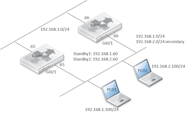
セカンダリアドレスで HSRP が可能か試してみました。環境は下記のとおりです。
ルータは、CSR1000V IOS XE Version: 03.09.02.S を使用しました。
結論から言えば、上記の環境では、セカンダリアドレスで HSRP は可能でした。
アドレス不足により、同一のブロードキャストドメインに、複数の異なるサブネットを共存させたい際等に活用できそうです。ただし、運用管理上の観点から、多用は避けた方が良いかもしれません。
Router01 はプライマリアドレスを Active、セカンダリアドレスを Standby として認識。
Router01#show standby brief
                     P indicates configured to preempt.
                     |
Interface   Grp  Pri P State   Active          Standby         Virtual IP
Gi1         1    110 P Active  local           192.168.1.66    192.168.1.60
Gi1         2    90  P Standby 192.168.2.66    local           192.168.2.60
Router02 はプライマリアドレスを Standby、セカンダリアドレスを Active として認識。
Router02#show standby brief
                     P indicates configured to preempt.
                     |
Interface   Grp  Pri P State   Active          Standby         Virtual IP
Gi1         1    90  P Standby 192.168.1.65    local           192.168.1.60
Gi1         2    110 P Active  local           192.168.2.65    192.168.2.
Router01 設定例
Router01#show running-config interface gigabitEthernet 1
interface GigabitEthernet1
 ip address 192.168.2.65 255.255.255.0 secondary
 ip address 192.168.1.65 255.255.255.0
 standby 1 ip 192.168.1.60
 standby 1 priority 110
 standby 1 preempt
 standby 2 ip 192.168.2.60
 standby 2 priority 90
 standby 2 preempt
Router02 設定例
Router02#show running-config interface gigabitEthernet 1
interface GigabitEthernet1
 ip address 192.168.2.66 255.255.255.0 secondary
 ip address 192.168.1.66 255.255.255.0
 standby 1 ip 192.168.1.60
 standby 1 priority 90
 standby 1 preempt
 standby 2 ip 192.168.2.60
 standby 2 priority 110
 standby 2 preempt
以上
VMware スナップショットの注意点
VMware のスナップショットとは
スナップショットには、スナップショット作成時の仮想マシンの状態とデータが保存されます。仮想マシンのスナップショットを作成すると、特定の状態の仮想マシンのイメージがコピーおよび保存されます。スナップショットは、繰り返し同じ状態の仮想マシンに戻る必要があるが、複数の仮想マシンを作成したくないという場合に便利です。
…(中略)…
出典:VMware, Inc
スナップショットに含まれる情報
- 仮想マシンの設定:ディスクを含む、仮想マシン ディレクトリ
- 電源状態:パワーオン状態、パワーオフ状態、またはサスペンド状態
- ディスク状態:仮想ディスクの状態。
- メモリ状態(任意):仮想マシンのメモリの内容
VMware スナップショットの注意点
スナップショットを削除した際、仮想マシンが数分間停止する事象があったので、メモ。
参考:A snapshot removal can stop a virtual machine for long time (1002836)
スナップショット作成時の動作
スナップショットを作成すると、delta.vmdk が作成されます。
例えば、1つの仮想マシンとスナップショットのファイル構成は、下記のとおりです。
- disk.vmdk with extent disk-flat.vmdk
- disk-000001.vmdk with extent disk-000001-delta.vmdk
スナップショット作成後、この delta.vmdk で差分情報を収容していきます。
スナップショット削除時の動作
スナップショットを削除、または結合した場合、Consolidate Helper Snapshot と呼ばれるスナップショットが、ディスク I/O に比例して複数作成されます。
- disk.vmdk with extent disk-flat.vmdk
- disk-000001.vmdk with extent disk-000001-delta.vmdk
- disk-000002.vmdk with extent disk-000002-delta.vmdk
delta.vmdk と親ディスクである flat.vmdk は整合性保全のため、Read-only となり、データは、この Consolidate Helper Snapshot へ書き込まれます。しかし、最終的には、この Consolidate Helper Snapshot も flat.vmdk へマージしなければいけないため、この間仮想マシンが停止します。この事から、スナップショットを削除する際は、十分に注意して、ディスク I/O が極力少ない状況下で、実施する事を推奨します。
また、VMware 社は、スナップショットの保持について、72時間(3日)以上、保持しない事を推奨しています。
Best practices for virtual machine snapshots in the VMware environment (1025279)
Use no single snapshot for more than 24-72 hours.
スナップショットによる副作用
データストアに、NetApp ストレージを利用している場合は、次の点にも注意が必要です。
仮想マシンのスナップショットは、512Byte で差分を管理しているため、Partial Write が発生します。
Partial Write とは、4KBbyte 以下のデータに対して書き込みが発生した際(NetApp の仕様上)直接書き込みする事はできないため、対象のブロックを一度読み出し、部分的更新を行ってから、ディスク書き込む処理の事です。このため、スナップショットが存在している場合、無駄な Read が発生していると考えられます。
以上