VMwareMirageの基本操作について
はじめに
VMware Mirage は、PC を以下の6つの論理レイヤーに分離し、管理します。
- ユーザーデータ設定レイヤー
- レジストリに対する構成の変更等、ユーザーが設定した状態が含まれます。
- ユーザーアプリケーションレイヤー
- ユーザーがインストールしたアプリケーションが含まれます。
- マシン ID レイヤー
- 一意の識別子、ホスト名等が含まれます。
- アプリケーションレイヤー
- 1つ以上の部署、または業務部門アプリケーションのセットが含まれます。
- ベースレイヤー
- OS、アンチウイルス、ファイアウォール及び、Office 等の主要アプリケーションが含まれます。
- ドライバライブラリレイヤー
- 固有のハードウェアで使用するためのドライバのグループが含まれます。
レイヤ管理の手順
エンドポイントの登録
左ペインの[Pending Devices]から対象の仮想マシンを選択し[Centralize Endpoint]をクリックします。

本例では[VMware Mirage Default CVD policy]を選択し[Next]をクリックします。

その他の設定は全てデフォルトを指定し[Finish]をクリックします。

左ペインの[CVD Inventory]から進捗を確認できます。

ベースレイヤの作成
左ペインの[Pending Devices]から対象の仮想マシンを選択し[Create Reference CVD]をクリックします。

[Base Layer]をクリックします。

その他の設定は全てデフォルトを指定し[Finish]をクリックします。

左ペインの[CVD Inventory]から進捗を確認できます。

アップロード処理が完了後、[Capture Base Layer]をクリックし、Base Layer の作成処理を開始します。

[Name]に Base Layer の名称を入力し[Next]をクリックします。

その他の設定は全てデフォルトを指定し[Finish]をクリックします。

左ペインの[CVD Inventory]から進捗を確認できます。

アップロード処理が完了後、左ペインの[Layers]からレイヤの詳細情報が確認できます。

OS マイグレーション
事前準備として、USMT を Mirage Server へインストールします。
Windows Automated Installation Kit for Windows 7 から[KB3AIK_EN.iso]をダウンロードします。
ダウンロードしたイメージをマウントし、インストールします。
デフォルトでは、以下のフォルダにインストールされます。
C:\Program Files\Windows AIK\Tools\USMT
次に USMT 4.0 update から HotFix をダウンロードします。
[Windows6.1-KB2023591-x64]を解凍後、4つのファイルを USMT のフォルダへ上書きコピーします。

Mirage Console を起動し左ペインの[System Configuration]から[USMT]タブをクリックします。
[Import USMT Folder]をクリックし、USMT をインストールしたフォルダを指定します。

以上で、Windows7 へマイグレートするために必要な USMT4.0 のインストールが完了しました。

Windows8/8.1 へマイグレートするためには、USMT6.3 をインストールする必要があります。
Windows ADK for Windows 8.1 Update から[adksetup.exe]をダウンロードします。
ダウンロードしたファイルを実行し、インストールします。
デフォルトでは、以下のフォルダにインストールされます。
C:\Program Files (x86)\Windows Kits\8.1\Assessment and Deployment Kit\User State Migration Tool
先の手順と同様に[Import USMT Folder]をクリックし、USMT をインストールしたフォルダを指定します。

以上で、Windows8/8.1 へマイグレートするために必要な USMT6.3 のインストールが完了しました。

左ペインの[CVD Inventory]から対象の仮想マシンを選択し[Migrate Windows OS]をクリックします。

[Download and Apply Base Layer]を指定し[Next]をクリックします。

ドメインの情報を設定します。本例では WORKGROUP を指定します。

その他の設定は全てデフォルトを指定し[Finish]をクリックします。

なお、USMT をインストールしていない場合、以下のエラーが出力されます。
USMT has not been imported to the server. VMware Mirage requires Microsoft USMT 6.3 for this operation.

マイグレーション実行後、クライアント側で再起動が必要です。

再起動後、Mirage により、Windows7→8.1のマイグレーションが実行されます。

マイグレート及び、ベースレイヤが適用が完了します。

ベースレイヤの適用
左ペインの[CVD Inventory]から対象の仮想マシンを選択し[Assign Base Layer]をクリックします。

適用するベースレイヤをリストから選択し[Next]をクリックします。

その他の設定は全てデフォルトを指定し[Finish]をクリックします。

なお、適用先とベースレイヤの OS が異なる場合は、下記のとおりエラーとなります。
OS Mismatch. Windows operating system mismatch between layer and CVD.

アップデートが完了し、クライアントで再起動した後、ベースレイヤが適用されます。

対象のエンドポイントに、適用したベースレイヤが表示されます。

アップレイヤの作成
左ペインの[Pending Devices]から対象の仮想マシンを選択し[Create Reference CVD]をクリックします。

[App Layer]をクリックします。

本例では[VMware Mirage Default CVD policy]を選択し[Next]をクリックします。

その他の設定は全てデフォルトを指定し[Finish]をクリックします。

左ペインの[CVD Inventory]から進捗を確認できます。

クライアント側でレコーディングアプリレイヤが起動します。

テストで、Tera Term/LogMeTT/TTLEditor をインストールします。

[Finalize App Layer Capture]をクリックし、レコード処理を完了します。

アプリケーションの内容を確認し[Next]をクリックします。

[Name]に App Layer の名称を入力し[Next]をクリックします。

その他の設定は全てデフォルトを指定し[Finish]をクリックします。

左ペインの[CVD Inventory]から進捗を確認できます。

アップロード処理が完了後、左ペインの[Layers]からレイヤの詳細情報が確認できます。

アップレイヤの適用
左ペインの[CVD Inventory]から対象の仮想マシンを選択し[Assign App Layer]をクリックします。

適用するアップレイヤを追加し[Next]をクリックします。

その他の設定は全てデフォルトを指定し[Finish]をクリックします。

アップデートが完了し、クライアントで再起動した後、アップレイヤが適用されます。

VMware Mirage について
VMware Mirage の概要
管理は集中、アプリケーションはローカルで実行
- 単一の PC イメージを IT 部門とエンドユーザー管理する論理レイヤに分離
- VDI のように共通のマスターイメージを物理 PC に配信可能
- ユーザーのデータやアプリケーションはマスターイメージで上書きされない
- ユーザーが誤って削除したファイルもユーザー自身でリストア可能

VMware Mirage の構築
検証環境
- VMware Mirage 5.4 を使用します。
- Mirage Server の OS 及び DB 領域として、ローカルドライブ(C:\)を使用します。
- Mirage Server はドメイン(example.com)に所属します。
- Mirage Gateway Server はドメインに所属しません。
- AD サーバに証明書サービスをインストールし、各サーバーへ証明書を発行します。
- データーベースとして、SQL2012 Express を使用します。
検証構成

Mirage Server の構築
.NET インストール
Mirage Server は .NET Framework を必要としますのでインストールします。

CSR 作成と証明書のインポート
「SSL サーバー証明書について」を参考に CSR 作成及び、証明書のインポートを行います。
SQL2012 Express インストール
以下の機能をインストールします。

インスタンス ID は「MRGDB」とします。

認証は「混合モード」を選択します。

Mirage Management Server インストール
先の手順で作成したインスタンス「MRGDB」を指定してインストールします。

Mirage Server インストール
先の手順で作成したインスタンス「MRGDB」を指定してインストールします。

IIS のインストール
「Mware Mirage インストールガイド」を参考に必要な機能をインストールします。
WebManagemnet インストール
デフォルトの内容(HTTP:7080、HTTPS:7443)でインストールします。

WebAccess インストール
デフォルトの内容(HTTP:6080、HTTPS:6443)でインストールします。

IIS 証明書バインド
「SSL サーバー証明書について」を参考に バインドの設定を行います。
Management Console インストール
インストール後、Management Console を起動します。

フォルダを右クリックし、「Add System on localhost」を選択します。

Mirage Server 及び Mirage Gateway を管理します。

Mirage Gateway の構築
CSR 作成
「SSL サーバー証明書について」を参考に CSR 作成及び、証明書(PFX 形式)のダウンロードを行います。
Mirage Gateway インストール
OVA をデプロイして起動後、以下のコマンドから基本設定を行います。
> sudo su -
# /opt/vmware/share/vami/vami_config_net
resolv.conf で nameserver を設定します。
# vi /etc/resolv.conf
nameserver 192.168.1.99
Mirage Gateway 設定
https://[MirageGatewayIP]:8443/WebConsole へアクセスします。
LDAP(本例では AD)を指定します。

Mirage Server を指定します。

先の手順でダウンロードした証明書をアップロードします。

Mirage Client のインストール
Mirage Client のインストール
本例では、Mirage Gateway の FQDN を指定してインストールします。

必要に応じて、Wanova.Desktop.Configurator.exe*1で設定を行います。

「Service」タブの「Detailed log」で、サーバとの接続ステータスを確認可能です。

一例として、サーバと接続が失敗した際のエラー内容と対処方法を以下に記載します。
- 接続が失敗し、下記メッセージが出力されている場合は、証明書の問題である可能性があります。例えば、ローカル PC の「信頼されたルート証明機関」に証明書がインポートされていない等が考えられます。
SslPolicyErrors: RemoteCertificateChainErrors
ERROR Wanova.Net.Transport.GenericSocketWrapper Exception caught during socket creation: The remote certificate is invalid according to the validation procedure
- 下記メッセージが出力されている場合は、証明書の内容と Mirage Client が指定したサーバ名に齟齬がある可能性があります。例えば、Mirage Gateway の FQDN ではなく、IP アドレスを指定している等が考えられます。
SslPolicyErrors: RemoteCertificateNameMismatch
ERROR Wanova.Net.Transport.GenericSocketWrapper Exception caught during socket creation: The remote certificate is invalid according to the validation procedure
*1:C:\Program Files\Wanova\Mirage Service\Wanova.Desktop.Configurator.exe
ESXi の証明書入れ替え
こちらを参考にさせて頂きました。
ESXi の証明書は以下のフォルダに配置されています。
~ # cd /etc/vmware/ssl
/etc/vmware/ssl # ls -l
total 8
-rw-r--r--    1 root     root          1428 Jan 13 06:55 rui.crt
-r--------    1 root     root          1708 Jan 13 06:55 rui.key
既存証明書のファイル名を変更します。
/etc/vmware/ssl # mv rui.crt rui.crt.old
/etc/vmware/ssl # mv rui.key rui.key.old
/etc/vmware/ssl # ls -l
total 8
-rw-r--r--    1 root     root          1428 Jan 13 06:55 rui.crt.old
-r--------    1 root     root          1708 Jan 13 06:55 rui.key.old
新しい証明書を同フォルダに配置します。
/etc/vmware/ssl # ls -l
total 16
-rw-r--r--    1 root     root          1428 Jan 13 06:55 rui.crt
-rw-r--r--    1 root     root          1428 Jan 13 06:55 rui.crt.old
-r--------    1 root     root          1708 Jan 13 06:55 rui.key
-r--------    1 root     root          1708 Jan 13 06:55 rui.key.old
Manegement Agents を再起動します。
/etc/vmware/ssl # /etc/init.d/hostd restart
/etc/vmware/ssl # /etc/init.d/vpxa restart
証明書が更新されると、vCenterからホストが切断されますので、再接続が必要です。
CentOS で FTP サーバ構築
検証用に FTP サーバが必要になったので、CentOS で構築した際のメモ。
こちらのサイトがとても分かりやすかったので、参考にさせて頂きました。
vsftpd インストール
[root@hostname ~]# yum -y install vsftpd
vsftpd.conf 設定
[root@hostname ~]# vi /etc/vsftpd/vsftpd.conf
anonymous_enable=NO			 <- 匿名ログイン禁止
ascii_upload_enable=YES			 <- コメントアウト:アスキーモードでの転送を許可
ascii_download_enable=YES		 <- コメントアウト:アスキーモードでの転送を許可
chroot_local_user=YES			 <- コメントアウト:chroot有効
chroot_list_enable=YES 			 <- コメントアウト:chroot有効
chroot_list_file=/etc/vsftpd/chroot_list <- コメントアウト:chroot リストファイル指定
ls_recurse_enable=YES			 <- コメントアウト:ディレクトリごと一括での転送有効
local_root=public_html			 <- 最終行へ追記:ルートディレクトリ指定
use_localtime=YES			 <- 最終行へ追記:ローカルタイムを使う
chroot_list 設定
[root@hostname ~]# vi /etc/vsftpd/chroot_list
ftpuser					 <- chroot を適用しないユーザーを追加
ユーザアカウント作成
[root@hostname ~]# useradd ftpuser
[root@hostname ~]# passwd ftpuser
ルートディレクトリ作成
[root@hostname ~]# mkdir /home/ftpuser/public_html
SELinux 無効化
[root@hostname ~]# setenforce 0
[root@hostname ~]# getenforce
※Enforcing:SELinux が有効の場合、クライアントからの接続時に下記エラーが出力される場合があります。
500 OOPS: cannot change directory:/home/user1
500 OOPS: priv_sock_get_cmd
接続がリモート ホストによって閉じられました。
vsftpd 再起動
[root@hostname ~]# /etc/rc.d/init.d/vsftpd start
vsftpd 起動設定
[root@hostname ~]# chkconfig vsftpd on
以上
VMware のマルチパス機構について
VMware のマルチパスについて
VMware のデフォルトのマルチパスプラグインは、NMP(Native Multi-Pathing Plugin)と呼ばれる汎用のマルチパスモジュールです。NMP は SATP(Storage Array Type Plugin)と PSP(Path Selection Plugin)で構成されます。
SATP
- 物理パスに関連付けられ、パスのフェイルオーバを制御します。
PSP
- どの物理パスを使用して I/O 要求を送信するかを処理します。
通常、VMware 社の互換性ガイドに記載のある PSP が自動で選択されますが、任意の PSP が適用されるようデフォルトを変更する事が可能です。
マルチパスの確認方法
SATP のリストは下記のコマンドで表示します。
~ # esxcli storage nmp satp list
Name                 Default PSP    Description
-------------------  -------------  ------------------------------------------
VMW_SATP_MSA         VMW_PSP_MRU    Placeholder (plugin not loaded)
VMW_SATP_ALUA        VMW_PSP_MRU    Placeholder (plugin not loaded)
VMW_SATP_DEFAULT_AP  VMW_PSP_MRU    Placeholder (plugin not loaded)
VMW_SATP_SVC         VMW_PSP_FIXED  Placeholder (plugin not loaded)
VMW_SATP_EQL         VMW_PSP_FIXED  Placeholder (plugin not loaded)
VMW_SATP_INV         VMW_PSP_FIXED  Placeholder (plugin not loaded)
VMW_SATP_EVA         VMW_PSP_FIXED  Placeholder (plugin not loaded)
VMW_SATP_ALUA_CX     VMW_PSP_RR     Placeholder (plugin not loaded)
VMW_SATP_SYMM        VMW_PSP_RR     Placeholder (plugin not loaded)
VMW_SATP_CX          VMW_PSP_MRU    Placeholder (plugin not loaded)
VMW_SATP_LSI         VMW_PSP_MRU    Placeholder (plugin not loaded)
VMW_SATP_DEFAULT_AA  VMW_PSP_FIXED  Supports non-specific active/active arrays
VMW_SATP_LOCAL       VMW_PSP_FIXED  Supports direct attached devices
PSP のリストは下記のコマンドで表示します。
~ # esxcli storage nmp psp list
Name           Description
-------------  ---------------------------------
VMW_PSP_MRU    Most Recently Used Path Selection
VMW_PSP_RR     Round Robin Path Selection
VMW_PSP_FIXED  Fixed Path Selection
デフォルトの PSP を Round Robin に変更したい場合は下記を実行します。
~ # esxcli storage nmp satp set -s VMW_SATP_DEFAULT_AA -P VMW_PSP_RR
Default PSP for VMW_SATP_DEFAULT_AA is now VMW_PSP_RR

~ # esxcli storage nmp satp list
Name                 Default PSP    Description
-------------------  -------------  ------------------------------------------
VMW_SATP_MSA         VMW_PSP_MRU    Placeholder (plugin not loaded)
VMW_SATP_ALUA        VMW_PSP_MRU    Placeholder (plugin not loaded)
VMW_SATP_DEFAULT_AP  VMW_PSP_MRU    Placeholder (plugin not loaded)
VMW_SATP_SVC         VMW_PSP_FIXED  Placeholder (plugin not loaded)
VMW_SATP_EQL         VMW_PSP_FIXED  Placeholder (plugin not loaded)
VMW_SATP_INV         VMW_PSP_FIXED  Placeholder (plugin not loaded)
VMW_SATP_EVA         VMW_PSP_FIXED  Placeholder (plugin not loaded)
VMW_SATP_ALUA_CX     VMW_PSP_RR     Placeholder (plugin not loaded)
VMW_SATP_SYMM        VMW_PSP_RR     Placeholder (plugin not loaded)
VMW_SATP_CX          VMW_PSP_MRU    Placeholder (plugin not loaded)
VMW_SATP_LSI         VMW_PSP_MRU    Placeholder (plugin not loaded)
VMW_SATP_DEFAULT_AA  VMW_PSP_RR     Supports non-specific active/active arrays
VMW_SATP_LOCAL       VMW_PSP_FIXED  Supports direct attached devices
なお、マルチパスのルールを確認するには下記を実行します。
~ # esxcli storage nmp satp rule list
Name                 Device  Vendor   Model             Driver  Transport  Options                     Rule Group  Claim Options                        Default PSP  PSP Options  Description
-------------------  ------  -------  ----------------  ------  ---------  --------------------------  ----------  -----------------------------------  -----------  -----------  --------------------------------------------------------------------------
VMW_SATP_MSA                          MSA1000 VOLUME                                                   system                                                                     MSA 1000/1500 [Legacy product, Not supported in this release]
VMW_SATP_ALUA                NETAPP                                        reset_on_attempted_reserve  system      tpgs_on                              VMW_PSP_RR                NetApp arrays with ALUA support
VMW_SATP_ALUA                IBM      2810XIV                                                          system      tpgs_on                              VMW_PSP_RR                IBM 2810XIV arrays with ALUA support
VMW_SATP_ALUA                IBM      2107900                              reset_on_attempted_reserve  system                                           VMW_PSP_RR
VMW_SATP_ALUA                IBM      2145                                                             system                                           VMW_PSP_RR
<...snip...>
マルチパスのルールを追加する場合は下記を実行します。
esxcli storage nmp satp rule add -V "Vendor" -M "Model" -e "Description"
以上
vSwitch でミラーリングを設定する
標準スイッチでは、分散スイッチと異なり、ポートをミラーリング機能をサポートしていませんが、任意の仮想マシンにパケットをミラーする事が可能です。
標準スイッチの作成
「Networking」タブで「Virtual switches」を選択し「Add host Networking」をクリックします。

「Virtual Machine Port Group for a Standard Switch」を選択し「Next」をクリックします。

「New Standard Switch」を選択し「Next」をクリックします。

試験のため NIC はアサインせず、「Next」をクリックします。

VLAN ID を「ALL(4095)」に指定し「Next」をクリックします。

内容を確認し「Finish」をクリックします。

標準スイッチが作成されている事を確認します。

仮想マシンへのポートグループ設定
現在、仮想マシンは分散スイッチのポートグループをアサインしているので、作成したスイッチへ移行します。
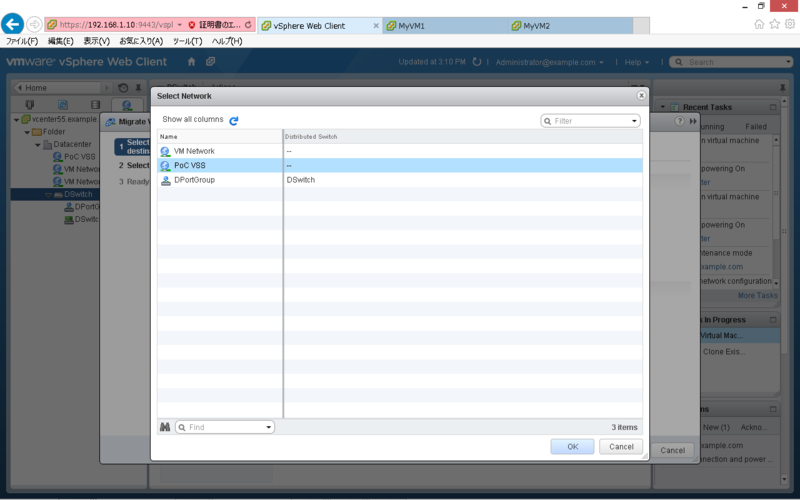
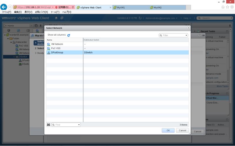
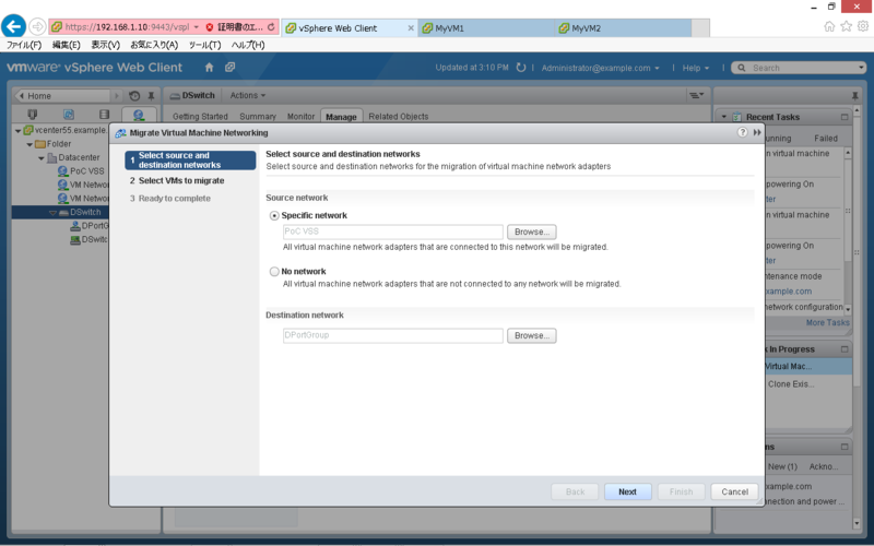
「Networking」タブで「DSwitch」を右クリックし「Migrate VM to Another Network」をクリックします。

Source Network の「Specific Network」で「Browse」をクリックします。

移行元(分散スイッチ)のポートグループを選択して「OK」をクリックします。

Destination Network の「Specific Network」で「Browse」をクリックします。

移行先(標準スイッチ)のポートグループを選択して「OK」をクリックします。

内容を確認し「Next」をクリックします。

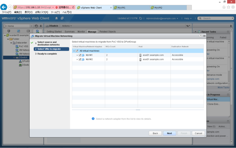
移行対象の仮想マシンを選択して「Next」をクリックします。

内容を確認し「Finish」をクリックします。

対象の仮想マシンが標準スイッチに移行している事を確認します。

ミラーリングの設定
テストのため、MyVM1 から MyVM3へ Ping し、MyVM2 で tcpdump を実行します。
現時点では、MyVM2 にパケットが転送されていません。

作成した仮想スイッチを選択し「Edit Settings」をクリックします。

「Security」の Promiscuous mode を「Accept」に変更し「OK」をクリックします。

MyVM2 にパケットが転送され、確認できるようになります。

Ontap シミュレーターで Flash Pool を試す
Flash Pool とは
HDD と SSD が混在したアグリゲートを構成し、使用頻度の高いデータを SSD のキャッシュへ集めることで、HDD へのアクセスを低減する機能になります。データを移動させるわけではなく、アクセス頻度の高いデータを ONTAP が自動で判別し、キャッシュされる事から、運用稼動は発生しません。
下記は、ユーザ数の増加に伴うスループットの傾向です。
出典:Tech OnTap
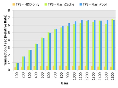
HDD のみで構成した場合、100ユーザの時点で HDD がボトルネックになり、スループットが頭打ちになっています。これに対して、Flash Pool を使用した場合は、ユーザの増加に伴い、スループットが向上しています。
Flash Pool の設定方法
ONTAP シミュレータで SSD Disk を擬似的に作成し、Flash Pool をを設定する際の手順になります。
SSD Disk の作成
Unlock the Diag user(7-Mode)
> priv set diag
*> useradmin diaguser unlock
*> useradmin diaguser password
Unlock the Diag user(Clustered Mode)
> set diag
*> security login unlock -username diag -vserver cluster1
*> security login password -username diag -vserver cluster1
Enter system shell(7-Mode)
*> systemshell
login: diag
Password:
%
Enter system shell(Clustered Mode)
*> systemshell -node cluster1-01
login: diag
Password:
%
Create SSD Disks(7-Mode/Clustered Mode)
% setenv PATH /sim/bin:$PATH
% cd /sim/dev
% sudo vsim_makedisks -t 35 -a 2 -n 14
% exit
Vefify the Disks(7-Mode)
*> disk show -n
*> sysconfig -r
Vefify the Disks(Clustered Mode)
*> disk show -container-type unassigned
*> system node run -node cluster1-01 sysconfig -r
Assign the Disks(7-Mode)
> disk assign v6.16
Assign the Disks(Clustered Mode)
> disk assign -disk v6.16 -owner cluster1-01
Flash Pool の有効化
Enable the Flash Pool(7-Mode)
> aggr options aggr1 hybrid_enabled on
> aggr add aggr1 -T SSD 14
Enable the Flash Pool(Clustered Mode)
> storage aggregate modify -aggregate aggr1 -hybrid-enabled true
> aggregate add-disks -aggregate aggr1 -disktype SSD -diskcount 14
Use the Flash Pool(7-Mode)
> vol create myvol aggr1 1g
Use the Flash Pool(Clustered Mode)
> volume create -vserver svm-01 -aggregate aggr1 -volume myvol -size 1g
以上
分散スイッチで Netflow を有効化する
Netflow は Cisco 社が開発した、ネットワークのトラフィックを収集・分析するための技術です。VMware 社の分散スイッチでは、NetFlow をサポートしており、ポートグループに流れるトラフィックを、コレクターに出力する事が可能です。
分散スイッチの設定
対象の分散スイッチを右クリックし「Manage Distributed Port Groups」をクリックします。

「Monitoring」を選択し「Next」をクリックします。

対象のポートグループを選択し「Next」をクリックします。

Netflow を「Enabled」に設定し「Next」をクリックします。

内容を確認し「Finish」をクリックします。

分散スイッチを選択し「Manage」タブの NetFlow で、コレクターの設定等を行います。

Netflow コレクタ(PRTG)の設定
「Sensors」タブから「Add Sensor」をクリックします。

「Create a new Device」を選択し「Continue」をクリックします。

Group を選択し「Continue」をクリックします。

「Device Name」「IP Address」を設定し「Continue」をクリックします。

「UDP port」「Active Flow Timeout」を設定し「Continue」をクリックします。

ポートグループ間のトラフィック状況をモニターする事が可能となります。

VMware PowerCLI サンプルスクリプト
CSV ファイルを読み込んで、仮想マシンを制御するスクリプトの例です。
本例では、仮想マシン名を記述した CSV ファイル(vms.csv)を以下のパスに配置しています。
C:\scripts\vms.csv
CSV ファイルの内容は、以下のとおりです。

仮想マシンを起動するスクリプト
$vCenterIP = "192.168.1.10"
$User = "Administrator"
$Password = "Password"
$VMs = Import-CSV C:\scripts\vms.csv

#Import the PowerCLI module
Add-PSSnapin VMware.VimAutomation.Core

#Connect to the server
$vi = Connect-VIServer -Server $vCenterIP -User $User -Password $Password

#Power on the VMs
foreach ($vm in $VMs){
      Get-VM $vm.VMName | where{$_.PowerState -eq "PoweredOff"} | Start-VM -Runasync -Confirm:$false | Out-Null
}

#Disconnect to the server
Disconnect-VIServer -Server $vCenterIP -Confirm:$False
仮想マシンを停止するスクリプト
$vCenterIP = "192.168.1.10"
$User = "Administrator"
$Password = "Password"
$VMs = Import-CSV C:\scripts\vms.csv

#Import the PowerCLI module
Add-PSSnapin VMware.VimAutomation.Core

#Connect to the server
$vi = Connect-VIServer -Server $vCenterIP -User $User -Password $Password

#Power off the VMs
foreach ($vm in $VMs){
      Get-VM $vm.VMName | where{$_.PowerState -eq "PoweredOn"} | Shutdown-VMguest -Confirm:$false | Out-Null
}

#Disconnect to the server
Disconnect-VIServer -Server $vCenterIP -Confirm:$False
仮想マシンのスナップショットを取得するスクリプト
$vCenterIP = "192.168.1.10"
$User = "Administrator"
$Password = "Password"
$Date = Get-Date -format yyyyMMddHHmm
$VMs = Import-CSV C:\scripts\vms.csv

#Import the PowerCLI module
Add-PSSnapin VMware.VimAutomation.Core

#Connect to the server
$vi = Connect-VIServer -Server $vCenterIP -User $User -

#Create the Snapshot
foreach ($vm in $VMs){
	  New-Snapshot -Name $Date -VM $vm.VMName -Descript
}

#Disconnect to the server
Disconnect-VIServer -Server $vCenterIP -Confirm:$False
仮想マシンのスナップショットを削除するスクリプト
$vCenterIP = "192.168.1.10"
$User = "Administrator"
$Password = "Password"
$Date = Get-Date -format yyyyMMddHHmm
$VMs = Import-CSV C:\scripts\vms.csv

#Import the PowerCLI module
Add-PSSnapin VMware.VimAutomation.Core

#Connect to the server
$vi = Connect-VIServer -Server $vCenterIP -User $User -Password $Password

#Remove the Snapshot
foreach ($vm in $VMs){
      Get-Snapshot -VM $vm.VMName | Remove-Snapshot -RemoveChildren -Confirm:$False
}

#Disconnect to the server
Disconnect-VIServer -Server $vCenterIP -Confirm:$False
参考書籍
リンク
以上
VMware Workstation で vFRC を試す
vFRC とは
仮想ディスクの Read Cache として、ローカルサーバの SSD を利用する仕組みを提供します。この機能により、仮想ディスクの読み込み速度が向上し、ストレージの負荷を軽減することが可能です。
詳細については、こちらをご参照ください。
事前準備
VMware Workstation では、SSD デバイスをシミュレートすることが可能です。対応する仮想マシンの vmx ファイルを編集し、SSD をシミュレートしたい SCSI デバイスを対象に下記を追記します。
scsiX:Y.virtualSSD = 1
対象の SCSI デバイスが SSD として、認識されます。
ESXi 側の vFRC の設定
Manage > Settings > Virtual Flash Resource Management > Add Capacity をクリックします。

有効な SSD デバイスが表示されるので、選択し「OK」をクリックします。

Device Backing のリストに SSD デバイスが追加されます。

ESXi ホストの vmkernel swap 領域として使用する場合は、下記の手順で行います。
Manage > Settings > Virtual Flash Host Swap Cache Configuration > Edit をクリックします。

キャッシュ容量を指定し「OK」をクリックします。

ホストキャッシュが設定されていることを確認します。

仮想マシン側の vFRC の設定
対象の仮想マシンの編集から、仮想ディスクを展開し vFRC の「Advanced」をクリックします。

キャッシュ容量とブロックサイズを指定し「OK」をクリックします。

「OK」をクリックします。

なお、この手順は、仮想マシンがパワーオン状態でも実施可能です。
vSphere Replication について
任意の仮想マシンについて、ハイパーバイザレベルでレプリケーションを実施する機能になります。
仮想マシンのコピーをハイパーバイザレベルで実施するため、データストアに依存しない点が特徴になります。

初期設定
vSphere Replication をインストール後、必要に応じて基本設定を行います。
仮想アプライアンスへの下記のアドレス・ポートでアクセス可能です。
https://IP_of_your_VR_appliance:5480

仮想アプライアンスを起動後、vCenter に VR のアイコンが追加されます。

Replication の構成例
対象の仮想マシンを選択し、右クリックから「Configure Replication」をクリックします。

vSphere Replication Server を選択し「Next」をクリックします。

Replication 先のデータストアを選択し「Next」をクリックします。

HDD をコピーする場合は「Enable disk replication」を選択し「Next」をクリックします。

「Next」をクリックします。

RPO(Recovery Point Objective)を設定し「Next」をクリックします。*3

内容を確認し「Finish」をクリックします。

Monitor > vSphere Replication > Outgoing Replication から、状態を確認できます。

仮想マシンのリカバリ
対象の仮想マシンを選択し、右クリックから「Recover」をクリックします。

Recovery options を選択し「Next」をクリックします。

仮想マシンの配置先 Folder を選択し「Next」をクリックします。

仮想マシンの配置先 Cluster を選択し「Next」をクリックします。

内容を確認し「Finish」をクリックします。

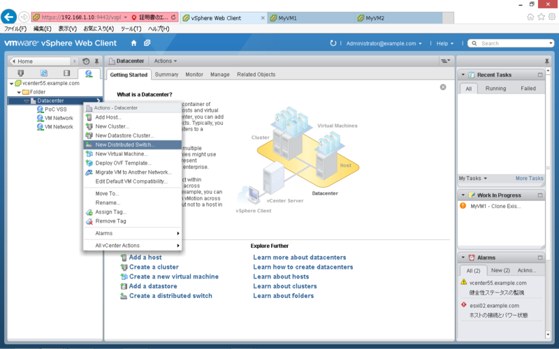
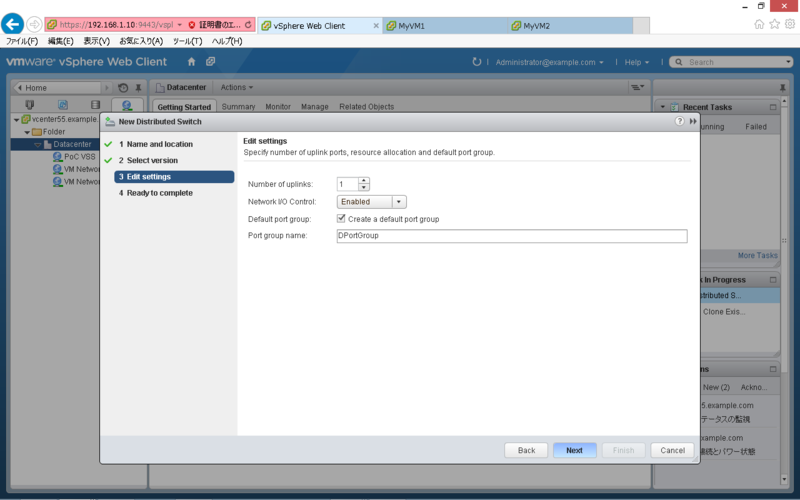
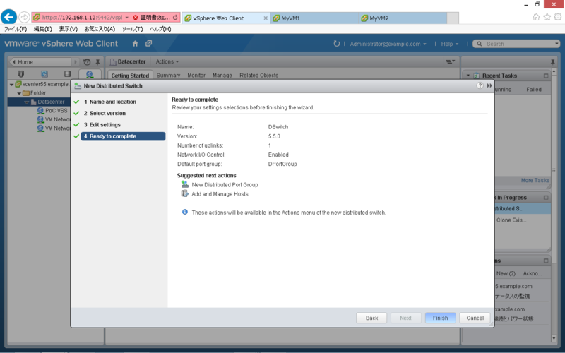
分散スイッチの作成とマイグレート
vSphere Web Client を使用した分散スイッチの作成と、標準スイッチからの移行を試してみました。
分散スイッチの作成
「Networking」タブで「Datacenter」を右クリックし「New Distributed Switch」をクリックします。
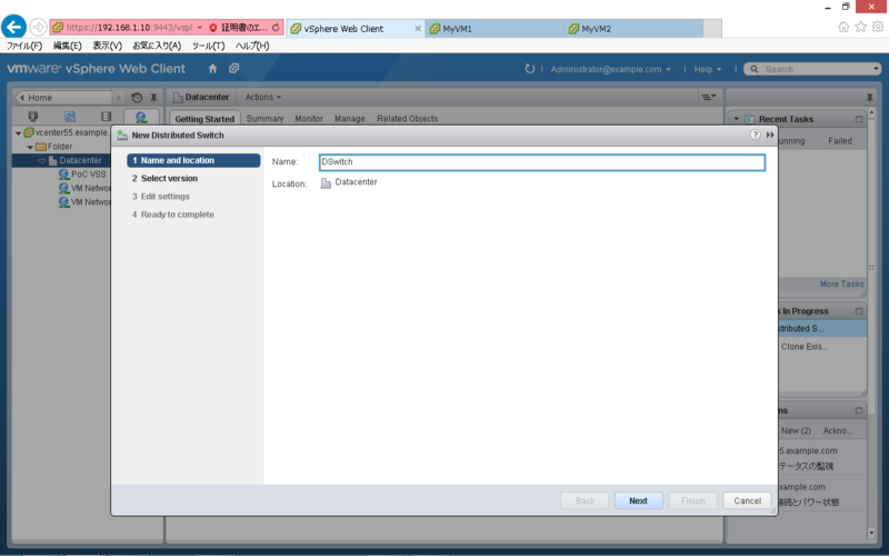
「Name」を設定し「Next」をクリックします。
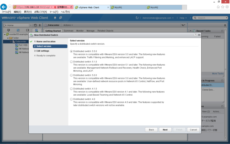
「Version」を指定し「Next」をクリックします。
「Port group name」等を設定し「Next」をクリックします。
内容を確認し「Finish」をクリックします。
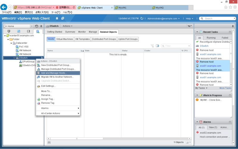
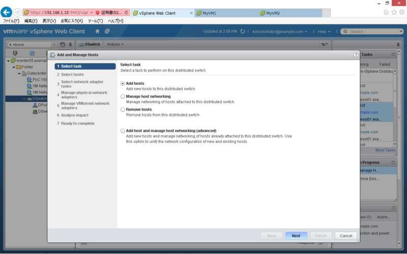
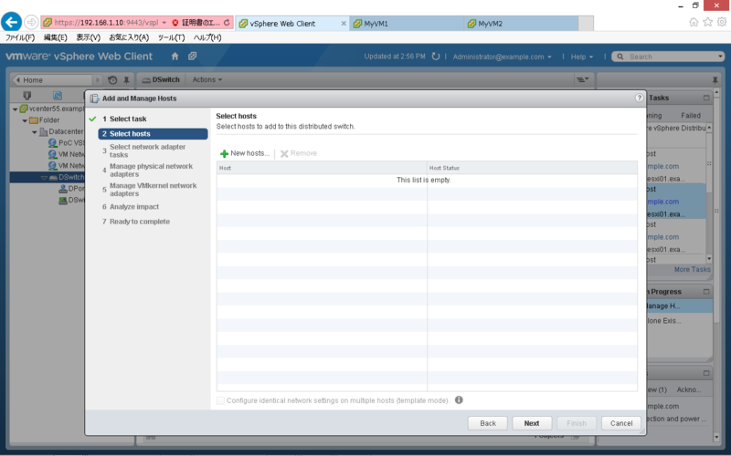
分散スイッチへのホスト登録
「Networking」タブで「DSwitch」を右クリックし「Add and Manage Hosts」をクリックします。
「Add hosts」を指定し「Next」をクリックします。
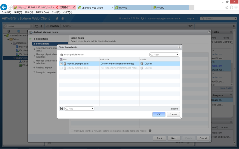
「New hosts」をクリックします。
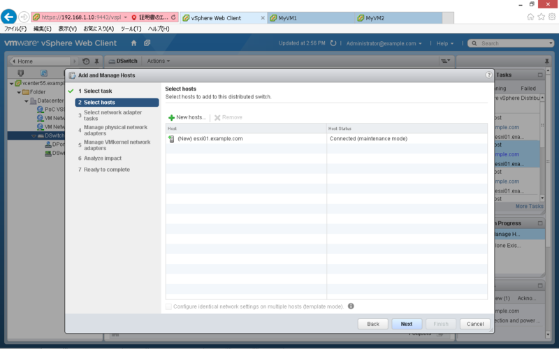
「Host」を選択し「OK」をクリックします。
内容を確認し「Next」をクリックします。
「Next」をクリックします。
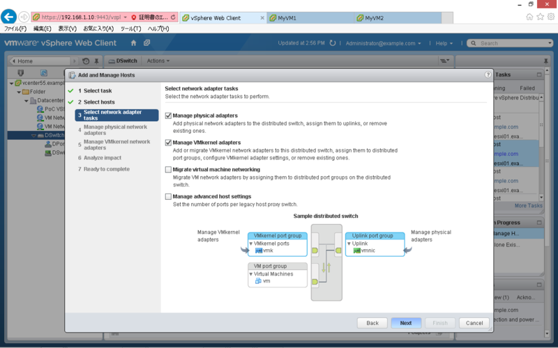
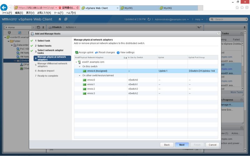
分散スイッチに追加する仮想 NIC を選択し「Assign uplink」をクリックします。
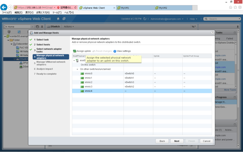
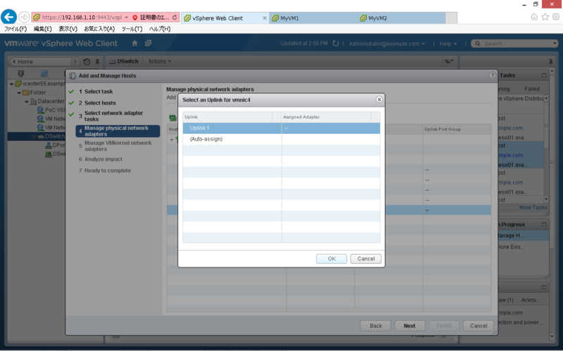
仮想 NIC を紐づける Uplink を選択し「OK」をクリックします。
内容を確認し「Next」をクリックします。
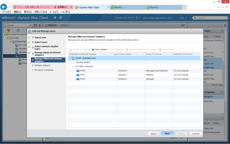
既存の vmkernel は移行対象外なので「Next」をクリックします。
「Next」をクリックします。
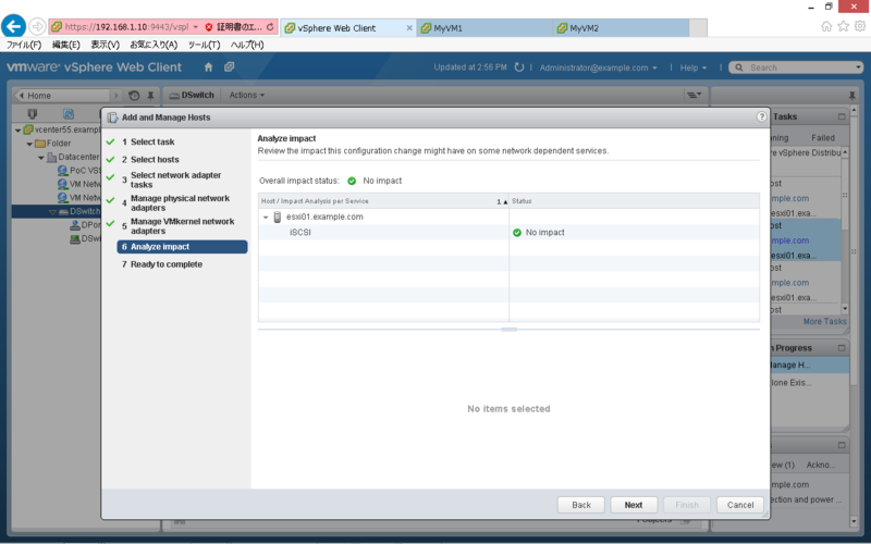
内容を確認し「Finish」をクリックします。
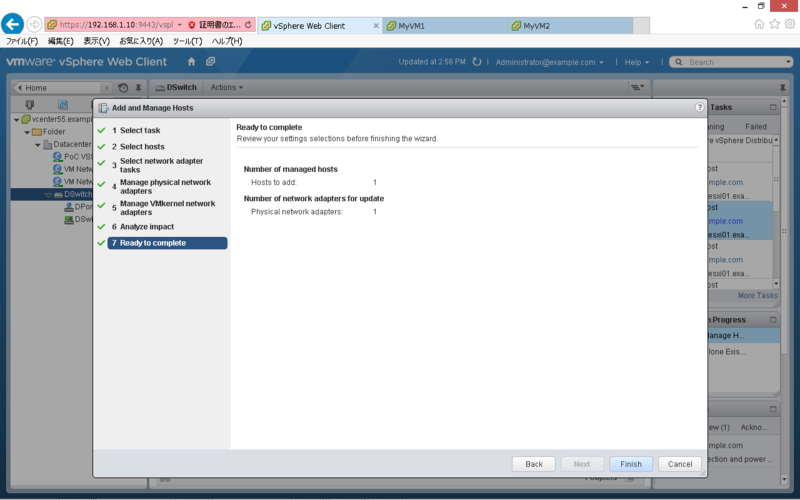
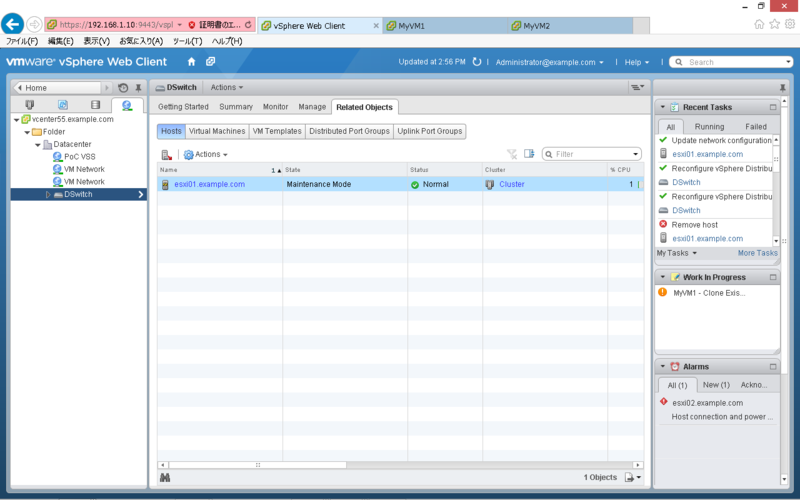
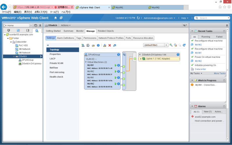
分散スイッチにホストが追加されている事を確認します。
標準スイッチから分散スイッチへの移行
「Networking」タブで「DSwitch」を右クリックし「Migrate VM to Another Network」をクリックします。
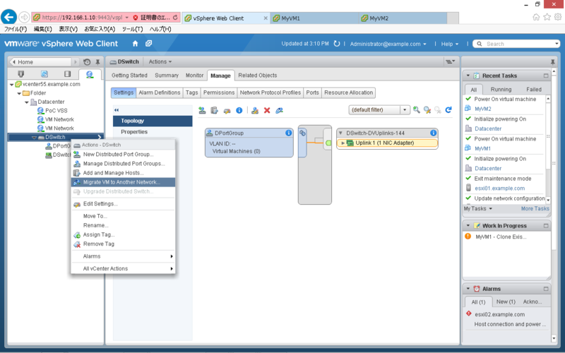
Source Network の「Specific Network」で「Browse」をクリックします。

移行元(標準スイッチ)のポートグループを選択して「OK」をクリックします。
Destination Network の「Specific Network」で「Browse」をクリックします。

移行先(分散スイッチ)のポートグループを選択して「OK」をクリックします。
内容を確認し「Next」をクリックします。
移行対象の仮想マシンを選択して「Next」をクリックします。
内容を確認し「Finish」をクリックします。
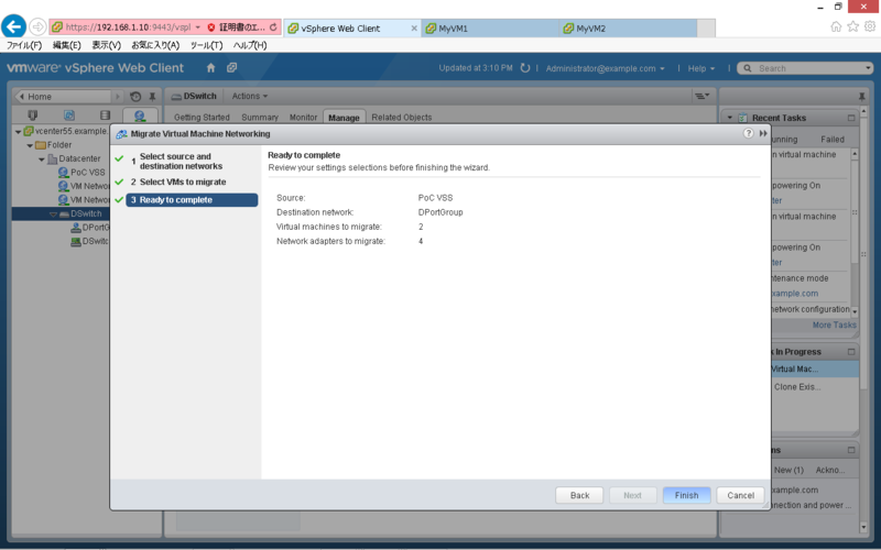
対象の仮想マシンが分散スイッチに移行している事を確認します。
busy,LUNs 状態の Snapshot について
SnapManager for Exchange (SME) 等のベリファイ処理失敗時に、残存する Snapshot になります。
以下の手順で削除する事が可能です。
snap list コマンドで busy 状態の Snapshot を確認します。
> snap list testvol
Volume testvol
working...

  %/used       %/total  date          name
----------  ----------  ------------  --------
<...snip...>
 56% (12%)   26% ( 3%)  Dec 18 05:01  exchsnap__exchange_02-23-2009_05.00.40 (busy,LUNs)
Snapmirror の送信元/送信先で Clone LUN が存在する事を確認します。
> lun show
<...snip...>
/vol/testvol/{3fd1acat-346c-216d-b6e4-bdf90a52801f}.rws
Snapmirror 送信先で snapmirror break を実行します。
> snapmirror break testvol
Snapmirror 送信先で lun offline/lun destroy を実行します。
> lun offline /vol/testvol/{3fd1acat-346c-216d-b6e4-bdf90a52801f}.rws
> lun destroy /vol/testvol/{3fd1acat-346c-216d-b6e4-bdf90a52801f}.rws
SnapDrive にて、Clone LUN をマウントしている場合は、Disconnect Disk を実行します。
Snapmirror 送信元で不要な Snapshot を削除します。
> snap delete testvol exchsnap__exchange_02-23-2009_05.00.40
Snapmirror resync を実行します。
> snapmirror resync -S [Sorce]:testvol testvol
以上
sdw_cl_vol について
sdw_cl_vol について
SnapManager for Exchange (SME) 等のベリファイ時に、ミラー先で生成されるボリュームです。
ベリファイ成功時は自動で削除されますが、失敗時は残留する場合があります。
これが残留していると、対象の Snapshot が busy 状態となり、次回のベリファイも失敗する可能性があります。
ボリューム名は、sdw_cl_[volname]_0 で生成されます。
> df -h
Filesystem               total       used      avail capacity  Mounted on
/vol/sdw_cl_testvol_0/      100GB       50GB      50GB      50%  /vol/sdw_cl_testvol_0/
/vol/sdw_cl_testvol_0/.snapshot        0KB    1000KB        0KB     ---%  /vol/sdw_cl_testvol_0/.snapshot
対象ボリュームの Snapshot 状況を確認すると、busy 状態の Snapshot が存在します。
> snap list testvol
Volume testvol
working...

  %/used       %/total  date          name
----------  ----------  ------------  --------
  0% ( 0%)    0% ( 0%)  Jan 16 06:12  netapp(0151729559)_testvol.1747
  0% ( 0%)    0% ( 0%)  Jan 16 06:12  @snapmir@{93F9293E-17BB-4AF5-91D6-FBEFBDCFCCFE}
  0% ( 0%)    0% ( 0%)  Jan 16 06:01  exchsnap__exchange_01-01-2015_06.00.46 (busy,snapmirror,vclone)
以下のコマンドで、sdw_cl_vol を削除します。
> vol offline sdw_cl_testvol_0
> vol destroy sdw_cl_testvol_0
対象ボリュームの Snapshot 状況を確認すると、busy 状態の Snapshot が削除されています。
> snap list testvol
Volume testvol
working...

  %/used       %/total  date          name
----------  ----------  ------------  --------
  0% ( 0%)    0% ( 0%)  Jan 16 06:12  netapp(0151729559)_testvol.1747
  0% ( 0%)    0% ( 0%)  Jan 16 06:12  @snapmir@{93F9293E-17BB-4AF5-91D6-FBEFBDCFCCFE}
以上
vSphere Web Client でゲストへ接続できない問題について
vSphere Web Client で仮想マシンのコンソールを開く際、下記のように「サーバ名を解決できませんでした」というエラーが表示される場合があります。

考えられる原因の1つとして、クライアントから vCenter 及び、ESXi サーバの名前解決ができていない可能性があります。この場合、DNS を使用するか、下記のように hosts に登録する事で収束します。
# Copyright (c) 1993-2009 Microsoft Corp.
#
# This is a sample HOSTS file used by Microsoft TCP/IP for Windows.
#
# This file contains the mappings of IP addresses to host names. Each
# entry should be kept on an individual line. The IP address should
# be placed in the first column followed by the corresponding host name.
# The IP address and the host name should be separated by at least one
# space.
#
# Additionally, comments (such as these) may be inserted on individual
# lines or following the machine name denoted by a '#' symbol.
#
# For example:
#
#      102.54.94.97     rhino.acme.com          # source server
#       38.25.63.10     x.acme.com              # x client host

# localhost name resolution is handled within DNS itself.
#	127.0.0.1       localhost
#	::1             localhost
	192.168.1.10    vcenter55.example.com
	192.168.1.11	esxi01.example.com
	192.168.1.12	esxi02.example.com